
Related Manuals for Charder MS4910


Summary of Contents for Charder MS4910
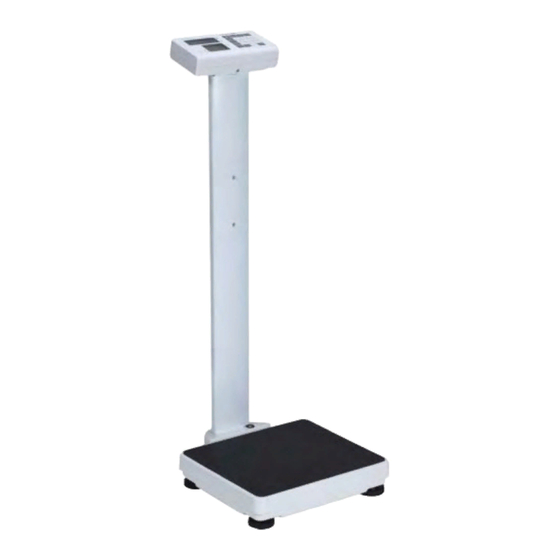
- Page 1 USER MANUAL MS4910 Stand-on Floor Scale Please keep the instruction manual at hand all the time for future reference.
- Page 2 Explanation of Graphic Symbols on Label/Packaging Caution, consult Separate collection for accompanying documents waste of electrical and before use electronic equipment, in accordance with Directive 2002/96/EC Manufacturer of medical Manufacturing year of device medical device Carefully read user manual Medical electrical before installation and equipment with Type B usage, and follow...
- Page 3 Copyright© Charder Electronic Co., Ltd. All rights reserved. This user manual is protected by international copyright law. All content is licensed, and usage is subject to written authorization from Charder Electronic Co., Ltd. (hereinafter Charder) Charder is not liable for any damage caused by a failure to adhere to requirements stated in this manual.
-
Page 4: Table Of Contents
CONTENTS I. Safety Notes ................5 A. General Information ............5 B. EMC Guidance and Manufacturer's Declaration ......8 II. Installation ................12 A. Assembly ................12 B. Inserting Batteries .............15 C. Using Adapter ..............17 D. Attaching Height Rod to Column ..........18 E. -
Page 5: Safety Notes
I. Safety Notes A. General Information Thank you for choosing this Charder Medical device. It is designed to be easy and straightforward to operate, but if you encounter any problems not addressed in this manual, please contact your local Charder service partner. - Page 6 All maintenance, technical inspections, and repairs should be conducted by an authorized Charder service partner, using original Charder accessories and spare parts. Charder is not liable for any damages arising from improper maintenance or usage. Disposal This product is not to be treated as regular household waste, but ...
- Page 7 Do not under any circumstances dismantle or alter the device, as this could result in electric shock or injury as well as adversely affect the precision of measurements. Do not place the device in direct sunlight, or in close proximity to an intense heat source.
-
Page 8: Emc Guidance And Manufacturer's Declaration
B. EMC Guidance and Manufacturer's Declaration Guidance and manufacturer’s declaration-electromagnetic emissions The MS4910 Stand-on Floor Scale is intended for use in the electromagnetic environment specified below. The customer or the user of the device should assure that it is used in such an environment. - Page 9 NOTE UT is the a.c. mains voltage prior to application of the test level. Guidance and manufacturer’s declaration-electromagnetic immunity The MS4910 Stand-on Floor Scale is intended for use in the electromagnetic environment specified below. The customer or the user of the device should assure that is used in such an environment.
- Page 10 80MHz to 2,7 GHz the frequency of the transmitter. 3 V/m 80MHz to 2,7 Recommended separation distance: d = 1,2 √P d = 1,2 √P 80MHz to 800 MHz d = 2,3 √P 800MHz to 2,5 GHz Where P is the maximum output power rating of the transmitter in watts (W) according to the transmitter manufacturer and d...
- Page 11 Recommended separation distance between portable and mobile RF communications equipment and the MS4910 Stand-on Floor Scale The device is intended for use in an electromagnetic environment in which radiated RF disturbances are controlled. The customer or the user of the device can help prevent...
-
Page 12: Installation
II. Installation A. Assembly Standard Column 1. Fasten and tighten four screws at the bottom of the base. Ensure four adjustable feet and stability foot are at same level before using device. Four screws Castor wheel column 1. Fasten and tighten four screws at the bottom of the base... - Page 13 2. Ensure four adjustable feet and stability foot are at the same level before using the device. Rotate counter-clockwise to extend, clockwise to retract Adjustable feet Stability foot...
- Page 14 3. Retract stability foot before moving device using castor wheels Note: rotate counter-clockwise to extend, clockwise to retract Ensure stability foot is retracted before using castor wheels...
-
Page 15: Inserting Batteries
B. Inserting Batteries 1. Open battery housing cover 2. Accessing batteries Take out the battery housing 3. Use either rechargeable battery pack, or AA batteries 4. Ensure batteries are installed into the housing correctly... - Page 16 Rechargeable Battery Housing AA-size Battery Housing 5. Install the battery housing into the compartment, and make sure the right side of housing pin is facing towards inside of the connecting position...
-
Page 17: Using Adapter
6. Slide back the cover to close the battery housing compartment. Turn on power to confirm that battery is correctly installed. Using Rechargeable Battery (optional) The rechargeable battery should be recharged at least once every 3 months, regardless of if the device has been used. Battery can be charged by plugging device's exclusive adapter into AC Connector Port. -
Page 18: Attaching Height Rod To Column
D. Attaching Height Rod to Column Standard (Narrow) Column Step 1. Attach two fixing blocks to Step 2. Attach height rod to blocks column using four flat-head using two flat-head screws screws Item Name Quantity Fixing block screws Fixing blocks Height Rod to fixing block screws... - Page 19 Castor Wheel Column 1. Attach brackets to column with 2. Attach height rod to brackets round-head screws using flat-head screws Item Name Quantity M5x0.8x11 round head screw Relief Bushing Bracket for HM200D/HM201D/HM201M Height Rod (Compatible with: HM200D/HM201D/HM201M) M5x10L flat head screw Fixing block M5x0.8x11...
- Page 20 Connecting height rod to indicator (HM200D/HM201D) Secure excess cable to column Digital height rod data transmission port on indicator...
-
Page 21: Attaching Thermal Printer
E. Attaching Thermal Printer Standard (Narrow) Column Washer head screw M5*0.8*15mm Cross head screw M4*0.7*6mm... - Page 22 Castor Wheel Column Print Button Printer Bracket Screws for Printer Bracket Screws for Bracket Item Parts M5*15L head screw Screws for printer bracket Printer bracket TP2100/TP2110 Thermal Printer 1 (purchased separately)
- Page 23 1. Install the side bracket 2. Install the thermal printer on the bracket...
-
Page 24: Indicator
III. Indicator A. Indicator and Key Functions (Wireless functionality optional) Key Function ON/OFF: Power on or power off. ZERO: Reset display to 0.0 kg display. Press and hold for 3 seconds to enter device settings. M1-5: Saving pre-tare values (up to 5) PRE-TARE: Pre-tare the known weight of an object (ex: chair) before beginning measurement. -
Page 25: Display Layout
CLEAR: Clear incorrect data input. ENTER: Confirm input B. Display layout Definitions Stable symbol: Indicate that weight is stable. Zero symbol: Weight is at zero Negative weight: Weight under zero. Low battery: Battery needs to be charged or replaced. -
Page 26: Using Device
IV. Using Device A. Basic Operation Switch on the device using key. The device will automatically perform self-calibration, displaying software version. Once "0.00 kg" appears on indicator, device is ready for measurement. Note: If "0.00 kg" does not display on indicator, press key to zero the device. -
Page 27: Tare
3. Enter height using numeral keys (ex: 170 cm). Input will automatically move to next digit. Press key to re-input. Press key to manually move to next digit. 4. After inputting height, press to confirm. 5. Proceed to weigh subject as usual. Indicator will display weight, height, and BMI. -
Page 28: Pre-Tare
2. Press key after stable symbol appears on indicator. Display will indicate "0.00 kg". 3. Guide subject (plus tared object) to be weighed upon measurement platform. Conduct measurement. 4. To clear tare value, remove all objects from measurement platform, and press key. - Page 29 Press key to store pre-tare weight; the indicator will make a beep sound. B. Input Manually DESCRIPTION EXAMPLE Press key. Left-most digit will begin blinking. If no further action is taken within 6 seconds, indicator will return to normal mode While digit is blinking: Enter pre-tare weight using 0~9 keys.
- Page 30 To save this pre-tare weight value in memory: Press key; the blinking "m" symbol will appear on the display. Press numeral key 1 ~ 5 to assign this number with the current pre-tare weight. Press key to store pre-tare weight; the indicator will make a beep sound.
-
Page 31: Print
Press key to confirm which pre-tare weight to select; the device will automatically deduct pre-tare weight. Press key to return to Normal Mode NOTE: Pre-tare weight must be under max capacity, otherwise screen will show 0.00 after key is pressed, and the operator will have to re-input pre-tare settings. -
Page 32: Device Setup
V. Device Setup A. Setting Time & Date Press and hold key for 3 seconds to enter Time Setting mode. Example: Inputting 2008, Dec 25, 8:00am Year Setting Enter year using numeral keys 0-9. Press key once completed to proceed to month & date setting. Month &... -
Page 33: Device Setup
B. Device Setup When the device is switched on, press and hold the key for about 3 seconds, until the display shows the "SETUP”, followed by "A.OFF” (first option in setting menu). In device setup menu: to toggle next menu option to toggle previous menu option to confirm selection / enter submenu Auto Power-Off: Instruct device to shut off automatically after a certain... - Page 34 Language: Set thermal printer language Press to toggle between English, Italian and Polish. Press key to confirm selection. Font size: Set thermal printer font size. Press to toggle between normal and double (larger). Press key to confirm selection. Bluetooth (optional): If device has Bluetooth module installed, Bluetooth function can be turned on or off.
-
Page 35: Setup Usb Connection To Pc
USB 2.0 or above. Operators should select a USB cable length that is most suitable to the operating environment. 1. Charder Smart Data Manager can be used to connect the device to a PC. The software program can be downloaded from the Charder website: [LINK URL] https://www.chardermedical.com/download.htm... - Page 36 Conducting Measurement 1. Input subject's first name, last name, patient ID, date of birth (DD/MM/YYYY), gender, and height (for BMI calculation) into software if needed. Press [Clear] to clear all input. NOTE: information can also be input after weight measurement. 2.
- Page 37 Saving & Printing Results 1. Press [Save as] to save measurement results as .csv file on PC. Default file name is same as user ID. (ex: 20190201.csv) To track changes and multiple measurements for the same subject, we recommend not changing the default file name. 2.
-
Page 38: Wireless Connection
3. Press the printer icon to print out result using a printer connected to the PC. VII. Wireless Connection If the device has the wireless module installed, the indicator can transmit measurement results wirelessly. Please see Charder wireless software instructions for details. -
Page 39: Troubleshooting
VIII. Troubleshooting Before contacting your local Charder distributor for repair service, we recommend considering the following troubleshooting procedures: Self-inspection 1. Device will not power on If battery power is depleted, replace with new batteries If batteries are not used, check if the power adapter is plugged into ... - Page 40 2. Indicator damage Possible hardware defects include: uneven brightness in LCD screen, blurred text, smeared rainbow screen, incorrect decimal display Unable to save or read data Indicator shows "ERRL" after device is switched on Keys not responding ...
-
Page 41: Product Specifications
IX. Product Specifications Model MS4910 Display DP3710 Capacity 300 kg x 0.1kg Accuracy ± 1.5e Weight Measurement OIML Class III LCD Screen 1.0-inch LCD screen (5 1/2 digits) Overall 360(W) x 480(D) x 1100(H) mm Platform 360(W) x 310(D) x 70(H) mm... - Page 42 Warning The device is only compatible with the power adapters specified below. DRAWING NO. CE APPROVED TYPE NO. TYPE Adapter plug VOLTAGE / MODEL NO. 12V 2A AD-8058(AD-0521) UE24WU-120200SPA AD-8057(AD-0520) UE24WV-120200SPA AD-8056(AD-0519) UE24WB-120200SPA AD-8074(AD-0534) UE24W4-120200SPAS...
- Page 43 Notes _______________________________________________________ _______________________________________________________ _______________________________________________________ _______________________________________________________ _______________________________________________________ _______________________________________________________ _______________________________________________________ _______________________________________________________ _______________________________________________________ _______________________________________________________ _______________________________________________________ _______________________________________________________ _______________________________________________________ _______________________________________________________ _______________________________________________________ _______________________________________________________ _______________________________________________________ _______________________________________________________ _______________________________________________________ _______________________________________________________...
-
Page 44: Declaration Of Conformity
2014/31/EU Non-automatic Weighing Instruments Directive Please see separate document showing on sticker of device for above CE marking. Authorized EU Representative: Manufactured by: Charder Electronic Co., Ltd. No.103, Guozhong Rd., Dali Dist., Taichung City, 41262 Taiwan (R.O.C.) CD-IN-1269 14214J 04/2021...
Need help?
Do you have a question about the MS4910 and is the answer not in the manual?
Questions and answers