Table of Contents
Advertisement
Quick Links
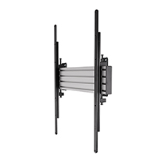
BT8321
Universal PORTRAIT
DIGITAL SIGNAGE Wall Mount
INSTALLATION GUIDE
SPECIFICATIONS
• Recommended for screens up to: 65" (165cm)
• Max load: 70kg (154lbs)
• Suitable for screens with VESA
up to 600 x 400mm
• Low profile design mounts screen 54mm (2.1") from wall
• Simple 'hook-on' installation with all mounting
hardware included
®
and non-VESA xings
www.btechavmounts.com
70kg
(154lbs)
TM
Advertisement
Table of Contents

Related Manuals for B-Tech SYSTEMX BT8321


Summary of Contents for B-Tech SYSTEMX BT8321
- Page 1 BT8321 Universal PORTRAIT DIGITAL SIGNAGE Wall Mount INSTALLATION GUIDE SPECIFICATIONS • Recommended for screens up to: 65" (165cm) • Max load: 70kg (154lbs) • Suitable for screens with VESA ® and non-VESA xings up to 600 x 400mm • Low profile design mounts screen 54mm (2.1") from wall •...
-
Page 2: Installation Safety Instructions
Please check carefully to make sure there are no missing or defective parts - defective parts must never be used. B-Tech AV Mounts, its distributors and dealers are not liable or responsible for damage or injury caused by improper installation, improper use or failure to observe these safety instructions. In such cases, all guarantees will expire. - Page 3 Untergrund montiert werden und darf nur bis zum angegebenen Höchstgewicht verwendet werden. B-Tech AV Mounts recommends that this product be installed by a quali ed AV technician or other suitably quali ed person . B-Tech AV Mounts, its distributors and dealers are not liable or responsible for damage or injury caused by improper installation , improper use or failure to observe these safety instructions.
- Page 4 BT8321 PARTS LIST PLEASE KEEP THIS FOR FUTURE REFERENCE...
-
Page 5: Installation Tools Required
FIXING KIT ITEM PART NAME (for xing mount to ceiling) WALL FIXING PLATE M8 x 12mm CSK SCREW M8 SLIDING NUT MOUNTING RAIL END CAP INTERFACE ARM 600mm ADAPTOR ARM M6 x 12mm SCREW 5AF HEX KEY 5AF LONG HEX KEY INTERFACE KIT M4 x 12mm SCREW M4 x 25mm SCREW... -
Page 6: Installation Instructions
INSTALLATION INSTRUCTIONS ATTACH WALL FIXING KIT TO MOUNTING RAIL i. Insert 2x item 3 into each end of item 4. 1 in the top channel and 1 in the bottom channel. - Page 7 ii. Fix item 1 to item 4 by fastening item 2 into item 3. Note: It is recommended to install the wall plates 400mm apart. (0.33") 400mm (15.75") 8.4mm Max Wall Fixing Distance Recommended Depth 35mm (1.38")
- Page 8 FIX MOUNTING RAIL TO THE WALL KEYHOLE MOUNTING i. Mark and drill 4 xing holes on the wall. ii. Insert item A1 into the top holes, do not fully tighten - allow a gap (approx. 10mm (0.4") 10mm) to hook on item 1. WALL (approx) 10mm...
- Page 9 ATTACH INTERFACE ARMS TO SCREEN i. For screens with VESA 600 x 400mm xings attach item 7 to item 6 using item 8. Note: Ensure the arms are facing the correct way round and the same holes are used on both arms. ii.
-
Page 10: Lateral Adjustment
HOOK SCREEN ONTO RAIL i. Hook the screen centrally onto item 4. If necessary, laterally adjust the screen left or right. WALL Lateral Adjustment SECURE SCREEN i. Optional: Once the screen is mounted, use the height adjustment screws on top of items 6 to level the screen. ii. -
Page 11: Wall Plate
TOP VIEW REAR VIEW 45mm 504mm WALL PLATE 8.4mm REAR VIEW 16mm 8.4mm 24mm 8.4mm 45mm 400mm These instructions are intended as a guide only and B-Tech accepts no liability for the accuracy of the information contained in this document. - Page 12 ©2023 B-Tech International Design and Manufacturing Ltd. All rights reserved. B-Tech AV Mounts is a division of B-Tech International Design and Manufacturing Ltd. B-Tech AV Mounts and the B-Tech logo are registered trade marks. All other brands and product names are trademarks of their respective owners.
Need help?
Do you have a question about the SYSTEMX BT8321 and is the answer not in the manual?
Questions and answers