Table of Contents
Advertisement
Ambient Weather WS-8480 FALCON Solar Powered Wireless
WiFi Remote Monitoring Weather Station User Manual
Table of Contents
1.
Introduction ..................................................................................................................................... 3
2.
Warnings ......................................................................................................................................... 3
3.
Getting Started ................................................................................................................................ 3
3.1
Parts List ................................................................................................................................. 3
3.2
Quick Start Guide ................................................................................................................... 3
3.3
Product Features ..................................................................................................................... 5
3.3.1
Display ............................................................................................................................... 5
3.3.2
Wireless Indoor Thermo-Hygrometer Transmitter ............................................................. 5
3.3.3
Sensor Array ....................................................................................................................... 7
3.4
Powering Up ........................................................................................................................... 8
3.4.1
Power Up Sequence ........................................................................................................... 8
3.4.2
Initial Sensor Synchronization ........................................................................................... 9
3.5
Mount the Indoor Sensor ........................................................................................................ 9
3.6
Mount the Outdoor Sensor Array ........................................................................................... 9
3.6.1
Site Survey ......................................................................................................................... 9
3.6.2
Pole Mounting the Sensor Array ...................................................................................... 10
4.
Console Display ............................................................................................................................ 11
5.
Settings .......................................................................................................................................... 11
5.17
Time Settings ........................................................................................................................ 11
5.1.1
Time Zone Settings .......................................................................................................... 13
5.18
Month Day vs. Year Display ................................................................................................ 14
5.19
Moon Phase .......................................................................................................................... 14
5.20
Sunrise and Sunset ............................................................................................................... 15
5.21
WiFi Connection Status ........................................................................................................ 15
5.22
Time Server Sync Status....................................................................................................... 15
5.23
Alarm Settings ...................................................................................................................... 16
5.1.2
Turning On and Off the Alarm Feature ............................................................................ 16
5.1.3
Setting the Alarm Time .................................................................................................... 16
5.1.4
Using the Alarm and Snooze Functions ........................................................................... 16
5.24
Temperature and Humidity Display and Settings ................................................................. 17
5.1.5
Temperature Units of Measure ......................................................................................... 17
5.1.6
Outdoor Sensor Array Signal Strength ............................................................................. 17
5.1.7
Indoor Sensor ................................................................................................................... 17
5.1.8
Temperature and Humidity Trend .................................................................................... 18
5.1.9
Temperature and Humidity Measurements Limits ........................................................... 19
5.25
Wind ..................................................................................................................................... 19
5.1.10
Average Wind Speed vs. Wind Gust ............................................................................ 19
5.1.11
Wind Units of Measure and Wind Direction Format ................................................... 19
5.1.12
Wind Speed Level Indicator ......................................................................................... 20
5.26
Barometric Pressure Display and Settings ........................................................................... 20
5.1.13
Barometric Pressure Units of Measure ........................................................................ 20
5.1.14
Absolute Pressure vs. Relative Pressure ...................................................................... 20
5.1.15
Relative Pressure Calibration ....................................................................................... 20
Version 1.2
©Copyright 2019, Ambient LLC. All Rights Reserved.
Page 1
Advertisement
Table of Contents

Subscribe to Our Youtube Channel
Related Manuals for Ambient Weather FALCON WS-8480


Summary of Contents for Ambient Weather FALCON WS-8480
-
Page 1: Table Of Contents
Ambient Weather WS-8480 FALCON Solar Powered Wireless WiFi Remote Monitoring Weather Station User Manual Table of Contents Introduction ............................. 3 Warnings ............................3 Getting Started ..........................3 Parts List ..........................3 Quick Start Guide ........................3 Product Features ........................5 3.3.1... - Page 2 5.27 The Forecast ......................... 21 5.28 Weather Index ........................21 5.29 Feels Like ..........................21 5.1.16 UV Index, Light Intensity and Sunburn Time .............. 22 5.1.17 Beaufort Scale ......................24 5.1.18 Wind Chill ........................25 5.1.19 Heat Index ........................26 5.1.20 Dew Point........................
-
Page 3: Introduction
1. Introduction Thank you for your purchase of the Ambient Weather WS-8480 FALCON Solar Powered Wireless WiFi Remote Monitoring Weather Station. The following user guide provides step by step instructions for installation, operation and troubleshooting. To download the latest full sized manual and additional troubleshooting tips, please visit: https://ambientweather.net/help/... - Page 4 Step Description Section Assemble and power up the sensor array Power up the indoor thermometer-hygrometer Power up the display console and synchronize with sensor array and thermo-hygrometer Mount the indoor sensor Mount the sensor array Set console settings Calibrate the relative pressure to sea-level conditions 5.1.15 (local airport) on console Reset the rain to zero on console (due to movement during...
-
Page 5: Product Features
Product Features 3.3.1 Display BARO Button WIND Button ALARM/SNOOZE button SUN button RAINFALL button LCD Display button INDEX / button HISTORY button MAX / MIN button CHANNEL button CLOCK SET button Wall suspension eye for hanging REFRESH button SENSOR / WIFI button RESET button °C / °F button ALARM button... - Page 6 Figure 2 Description Description [RESET] button Transmitter LED (flashes when the remote is transmitting) Suspension eye for hanging 2 x AA battery compartment Transmitter channel (assign the transmitter to 1, 2 ,3 ,4, 5, 6, or 7 default = 1) Note: The WS-8480 supports seven wireless channels.
-
Page 7: Sensor Array
3.3.3 Sensor Array Figure 3 Version 1.2 ©Copyright 2019, Ambient LLC. All Rights Reserved. Page 7... -
Page 8: Powering Up
Description Description [RESET] button Wind vane Wind cups Transmission status LED (flashes when transmits) Antenna Bubble level Thermo-hygrometer radiation shield Rain collector Thermo-hygrometer sensor UV / Light Intensity sensor Mounting pole bracket (fits 35 – 40 mm Solar panel diameter pole (1” – 1.75”) 3 x AA battery compartment Powering Up 3.4.1 Power Up Sequence... -
Page 9: Initial Sensor Synchronization
Note: If no display is present after powering up the console, press the [RESET] button on the back of the console with an open ended paper clip or sharp tool. 3.4.2 Initial Sensor Synchronization The console will automatically search for and connect to the indoor and outdoor sensors after it is powered up. -
Page 10: Pole Mounting The Sensor Array
Please take this into consideration when choosing console or mounting locations. Make sure your display console is at least five feet away from any electronic device to avoid interference. 6. Visit Ambient Weather Mounting Solutions for assistance and ideas for mounting your weather station: http://www.ambientweather.com/amwemoso.html 3.6.2 Pole Mounting the Sensor Array... -
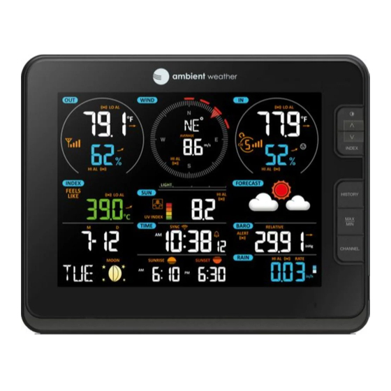
Page 11: Console Display
4. Console Display No Description No Description Outdoor temperature & humidity Barometer Forecast Wind direction & speed Calendar and moon phase Indoor temperature & humidity Time & Alarm Feels Like Temperature Heat Index & Wind Barometer Chill) Sun (UV, Light Intensity, Sunburn Time) Sunrise &... - Page 12 Command Mode Settings Image [CLOCK Enter Time Zone Press [ ] to increase, [ ] to SET] + 2 Settings decrease. Reference Figure seconds [CLOCKSET] Enter Daylight Press [ ] or [ ] to turn ON Savings Time or OFF. OFF (AZ and HI) or ON (everywhere...
-
Page 13: Time Zone Settings
[CLOCKSET] Day Press [ ] to increase, [ ] to decrease. [CLOCKSET] Month Day Press [ ] or [ ] to toggle Format between M-D (month-day) and D-M (day-month) [CLOCKSET] Enable or disable Press [ ] or [ ] to turn ON the internet time or OFF sync... -
Page 14: Month Day Vs. Year Display
Hours from Time Zone Cities -6 CST: Central Standard Chicago, IL, USA -5 EST: Eastern Standard New York, NY, USA -4 AST: Atlantic Standard Caracas -3 --- São Paulo, Brazil -2 AT: Azores Azores, Cape Verde Islands -1 WAT: West Africa 0 GMT: Greenwich Mean London, England WET: Western European... -
Page 15: Sunrise And Sunset
Figure 10 5.20 Sunrise and Sunset The console calculates your location’s sunrise and sunset time based on your time zone, latitude and longitude you entered. Figure 11 5.21 WiFi Connection Status When the console successfully connects to your Wi-Fi router, the Wi-Fi signal icon will appear in the time field on the LCD display. -
Page 16: Alarm Settings
Figure 12 5.23 Alarm Settings 5.1.2 Turning On and Off the Alarm Feature In normal mode, press the ALARM button to show the alarm time. Press the alarm button again, and the alarm icon will appear. Press the alarm button again, and the pre-alert icon will appear. -
Page 17: Temperature And Humidity Display And Settings
If the snooze function is turned on, the 4-step crescendo alarm will sound every 2 minutes. Press and hold the ALARM / SNOOZE button for two seconds to turn off the alarm sound. The alarm bell will stop flashing. 5.24 Temperature and Humidity Display and Settings 5.1.5 Temperature Units of Measure... -
Page 18: Temperature And Humidity Trend
Figure 16 5.1.7.2 Changing Indoor Channel Numbers The console supports up to seven wireless indoor/outdoor sensors. If you have two or more sensors, press the CHANNEL button to switch to different channels. Press and hold the CHANNEL button for two seconds to automatically scroll between the indoor channels every four seconds. -
Page 19: Temperature And Humidity Measurements Limits
5.1.9 Temperature and Humidity Measurements Limits When temperature is below -40 °C, (-40 °F), the LCD will display “Lo”. If temperature is above 80 °C (176 °F), LCD will display “HI”. When humidity is below 1%, the LCD will display “Lo”. If humidity is above 99%, the LCD will display “HI”. -
Page 20: Wind Speed Level Indicator
5.1.12 Wind Speed Level Indicator The wind speed level is based on the Beaufort scale, and is displayed at the botton of the WIND field: Figure 20 5.26 Barometric Pressure Display and Settings Note: The barometric pressure sensor is inside the console. Barometric pressure is the same inside or outside of your home or facility. -
Page 21: The Forecast
5.27 The Forecast Figure 21 The weather forecast or pressure tendency is based on the rate of change of barometric pressure. In general, when the pressure increases, the weather improves (sunny to partly cloudy) and when the pressure decreases, the weather degrades (cloudy to rain). When the pressure drops rapidly, the storm icon will be displayed. -
Page 22: Uv Index, Light Intensity And Sunburn Time
Figure 23 Note: The National Weather Service defines the maximum wind chill temperature of 40° F and a minimum heat index temperature of 80°F. We extend this range from 64 °F to 79 °F to make it more interesting to the end user by curve fitting the national weather service’s tables. 5.1.16 UV Index, Light Intensity and Sunburn Time The Sun field displays Light Intensity, UV Index and Sunburn Time. - Page 23 1. Press and hold the SUN button for two seconds and the units of measure will flash. 2. Press the [ ] button to switch the units of measure between Klux, Kfc and W/m 3. Press the SUN button to confirm and save settings. 5.1.16.2 Sunburn Time The sunburn time is calculated from UV.
-
Page 24: Beaufort Scale
Exposure level Color 0.1 to 2.9 Green 3.0 to 5.9 Moderate Yellow 6.0 to 7.9 High Orange 8.0 to 10.9 Very High ≥11.0 Extreme Purple Figure 27 5.1.17 Beaufort Scale The Beaufort Scale is an international scale of wind velocities ranging from 0 (calm) to 12 (Hurricane force). -
Page 25: Wind Chill
13 - 17 mph raised. Small branches begin to move. 11 - 16 knot 5.5 - 7.9 m/s Fresh breeze 29 - 38 km/h Branches of a moderate size move. 18 - 24 mph Small trees in leaf 17 - 21 knot begin to sway. -
Page 26: Heat Index
The wind chill calculation is only valid for temperatures less than 40 °F and wind speeds greater than 0 mph, according to the National Weather Service. Figure 30 5.1.19 Heat Index Heat Index is an index that combines air temperature and relative humidity, as an attempt to determine the human-perceived equivalent temperature. -
Page 27: Dew Point
Figure 33 5.1.20 Dew Point The dew point is the temperature below which the water vapor in air at constant barometric pressure condenses into liquid water at the same rate at which it evaporates. The condensed water is called dew when it forms on a solid surface. -
Page 28: Rainfall
5.30 Rainfall The rainfall displays total rain (since the last reset), hourly, daily, weekly, or monthly rain. Figure 35 Figure 36 5.1.21 Rain Units of Measure Command Mode Settings [RAIN] + 2 Enter Rain Settings Press [ ] to change between mm → inch seconds Rain Units of Measure Exit Rain Settings... -
Page 29: Resetting Rain To Zero
5.13.3 Resetting Rain to Zero In normal mode, press and hold the HISTORY button with 2 sec to reset the rainfall record. 5.14 Min / Max Press (do not hold) the MAX / MIN button on the front of the display to review the following: Command Parameter [MAX/MIN]... -
Page 30: Alerts
The LCD will also display the history icon history data records with the associated date and time . 5.16 Alerts This feature alerts you in the event that defined parameters are out of range. Once the alert is met, the alarm will sound and the parameter will flash. -
Page 31: Activating An Alert
Figure 37 8. After selecting the alert parameter, press and hold the ALERT buttons for 2 seconds to adjust, and the alert value will flash. 9. Press the [ ] or [ ] to adjust the alert value up or down, or press and hold the buttons to change rapidly. -
Page 32: Place Console In Access Point Mode
Place Console in Access Point Mode Place the console in Access Point mode by pressing and holding the WiFi / Sensor button on the back of the display for 6 seconds, until AP is flashing in the time field: Figure 39 Connect to the Console’s WiFi Server Note: You may be required to disconnect your computer’s ethernet cable from your router if it shares the same IP address 192.168.1.1. - Page 33 Figure 41 c) Example 3. Connect to the console WiFi server with an iPhone or iPad. Choose the Settings icon and Wi-Fi (Figure 42). Connect to the PWS- WiFi network, as shown in Figure 43 (your WiFi network name may be slightly different, but will always begin with PWS-).
- Page 34 Figure 44 Figure 45 1. Once connected, enter the following IP address into any browser’s address bar: http://192.168.1.1 to access the console’s web interface: Note: Some browsers will treat 192.168.1.1 as a search, so make sure you include the header http://, http://192.168.1.1 not 192.168.1.1 2.
- Page 35 Figure 46 Notes: • Make a note of your Mac address. You will need this to register at AmbientWeather.net. • Hidden SSIDs. If you have a hidden SSID, enter the SSID manually. • Finding your Longitude and Latitude. Visit Bing Maps: https://www.bing.com/mapspreview and enter your address.
-
Page 36: Register With Ambientweather.net
Figure 47 5. Once the setup is completed, the Wi-Fi console will disconnect from your computer or smart phone’s Wi-Fi connection, and search for the assigned router. If the connection is successful, the Wi-Fi console’s Wi-Fi icon will remain on. 6.1 Register with AmbientWeather.net Visit: www.AmbientWeather.net... -
Page 37: Additional Ambientweather.net Features
Register an account on AmbientWeather.net (email address and password). Once registered, select the dashboard to view your data, as shown in Figure 50. Figure 50 For a complete list of Ambient Weather apps, visit: https://ambientweather.net/help/community/ 6.2 Additional AmbientWeather.net Features 6.2.1 IFTTT The AmbientWeather.net service connects to IFTTT, the platform that allows devices and services to... -
Page 38: Compatible With Alexa
AmbientWeather.net. Enable the skill and get started: say "Alexa, ask Ambient Weather for a weather report.". This will provide you with your outdoor weather report, but you can ask for your indoor weather report as well by saying, "Alexa, ask Ambient Weather about the indoor conditions."... -
Page 39: Advanced Settings
Advanced Settings To view advanced settings, from the Setup panel (Figure 36), tap the ADVANCED tab. 6.4.1 Calibration The purpose of calibration is to fine tune or correct for any sensor error associated with the devices margin of error. Errors can occur due to electronic variation (example, the temperature sensor is a resistive thermal device or RTD, the humidity sensor is a capacitance device), mechanical variation, or degradation (wearing of moving parts, contamination of sensors). -
Page 40: Notes About Calibration
6.4.2 Notes About Calibration Parameter Type of Default Typical Calibration Source Calibration Temperature Offset Current Value Red Spirit or Mercury Thermometer (1) Humidity Offset Current Value Sling Psychrometer (2) Offset Current Value Calibrated laboratory grade Barometer barometer REL Barometer Offset Current Value Local airport (3) Wind Direction Offset... -
Page 41: Calibrating The Wind Direction For The Southern Hemisphere
Without a calibrated source, wind speed can be difficult to measure. We recommend using a calibrated wind meter (available from Ambient Weather) and a constant speed, high speed fan. (7) The rain collector is calibrated at the factory based on the funnel diameter. The bucket tips every 0.01”... -
Page 42: Maintenance
(Figure 51). From the Setup panel (Figure 36), tap the ADVANCED tab to update the firmware. The upload takes approximaetely 5-10 minutes. While updating, the status will be dispalyed in the wind direction field. Figure 52 7 Maintenance Figure 53 7.1 Battery Replacement When the low battery indicator is displayed, it indicates that the outdoor sensor or the current... -
Page 43: Adding Or Subtracting Sensors
8.1 Adding or Subtracting Sensors 1. Make sure each sensor is on a different channel and in sequence (1, 2, 3, ..) before powering up. Insert the batteries. If already powered up, press the reset button inside the battery compartment. Reference Section 3.3.2 for details. -
Page 44: Measurement Specifications
9.2 Measurement Specifications The following table provides specifications for the measured parameters. Measurement Range Accuracy Resolution Indoor and Outdoor -4 to 140 °F alkaline 131 to 140°F: ± 0.9°F 0.1 °F/°C Temperature batteries (55 to 60°C: ± 0.5°C) -40 to 140 °F Lithium 50 to 131°F: ±... -
Page 45: Other Specifications
versions of Chrome, Safari, IE, Edge, Firefox or Opera. 9.5 Other Specifications Time synchronize method: Synchronized through internet UTC time server • Console Temperature Limits of Operation: 23 ˚F to 122 ˚F (-5˚C to 50˚C) • 9.6 Weight Specifications Console: 1.3 lbs (590 grams) with batteries •... - Page 46 Problem Solution The wireless sensor communication has Make sure the transmitter is powered up and the • been lost or is intermittent or will not sync LED is flashing about once per 12 seconds. For cold weather environments, install lithium batteries.
-
Page 47: Liability Disclaimer
Problem Solution Console Time is off by increments of Make sure your time zone and Daylight Savings hours. Time are set properly (Reference Section 5.1.1). 11 Liability Disclaimer Please help in the preservation of the environment and return used batteries to an authorized depot. The electrical and electronic wastes contain hazardous substances. -
Page 48: Warranty Information
14 California Prop 65 WARNING: Use of the Ambient Weather Products can expose you to chemicals, including lead and lead compounds, which are known to the State of California to cause cancer and bisphenol A (BPA), and phthalates DINP and/or DEHP, which are known to the State of California to cause birth defects or other reproductive harm. - Page 49 Although our manufacturing process is "lead-free" and RoHS compliant, it remains possible that trace amounts of lead could be found in components or subassemblies of Ambient Weather Products. Bisphenol A (BPSA) could conceivably be present in minute amounts in our plastic housings, lenses, labels or adhesives, and DEHP &...
Need help?
Do you have a question about the FALCON WS-8480 and is the answer not in the manual?
Questions and answers