Table of Contents
Advertisement
Quick Links
One Technology Way • P.O. Box 9106 • Norwood, MA 02062-9106, U.S.A. • Tel: 781.329.4700 • Fax: 781.461.3113 • www.analog.com
Evaluating the
FEATURES
Fully featured evaluation board for the
PC software for control and data analysis (time domain)
EVALUATION KIT CONTENTS
EVAL-AD4115SDZ
AD411x Eval+
evaluation software
Plastic screw and washer set
SOFTWARE NEEDED
AD411x Eval+
EQUIPMENT NEEDED
Any of the following
SDP
hardware:
or
EVAL-SDP-CK1Z
(SDP-K1)
DC signal source
PC running Windows with USB 2.0 port
PLEASE SEE THE LAST PAGE FOR AN IMPORTANT
WARNING AND LEGAL TERMS AND CONDITIONS.
AD4115
Single Supply, 24-Bit, 125 kSPS, Sigma-Delta ADC
with ±10 V Inputs
AD4115
EVAL-SDP-CB1Z
(SDP-B)
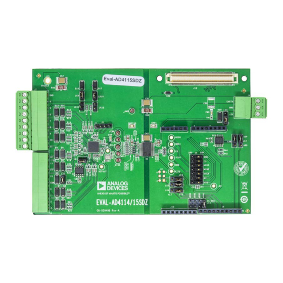
EVALUATION BOARD PHOTOGRAPH
Rev. 0 | Page 1 of 24
EVAL-AD4115SDZ
GENERAL DESCRIPTION
The EVAL-AD4115SDZ is a full featured evaluation board that
can evaluate all features of the AD4115. The
125 kSPS, Σ-Δ analog-to-digital converter (ADC) with a ±10 V
input voltage range (16 single-ended channels or eight fully
differential channels). All channels have on-board overvoltage
and overcurrent protection.
The EVAL-AD4115SDZ includes voltage references and power
and data insulation and can be connected to the Analog Devices,
Inc., system demonstration platform (SDP) hardware. The
board provides connection to a PC via a universal serial bus
(USB) port and can provide power for the EVAL-AD4115SDZ
from the PC USB port.
The
AD411x Eval+
functionality and provides dc time domain analysis in the form
of waveform graphs, histograms, and associated noise analysis
for ADC performance evaluation.
Full specifications for the
data sheet, which must be consulted in conjunction with this
user guide when working with the EVAL-AD4115SDZ.
Figure 1.
User Guide
AD4115
evaluation software configures the
AD4115
are available in the
UG-1820
is a 24-bit,
SDP
AD4115
AD4115
Advertisement
Table of Contents

Related Manuals for Analog Devices EVAL-AD4115SDZ


Summary of Contents for Analog Devices EVAL-AD4115SDZ
-
Page 1: Features
Plastic screw and washer set The EVAL-AD4115SDZ includes voltage references and power SOFTWARE NEEDED and data insulation and can be connected to the Analog Devices, Inc., system demonstration platform (SDP) hardware. The AD411x Eval+ board provides connection to a PC via a universal serial bus... -
Page 2: Table Of Contents
Revision History ................2 Configuration Tab ..............11 Evaluation Board Block Diagram ........... 3 Waveform Tabs ................13 EVAL-AD4115SDZ Quick Start Guide ......... 4 Histogram Tab ................15 Recommended Quick Start Guide ..........4 Register Map Tab (Advanced Mode Only) ......16 Quick Start Measurement ............ -
Page 3: Evaluation Board Block Diagram
EVAL-AD4115SDZ User Guide UG-1820 EVALUATION BOARD BLOCK DIAGRAM Figure 2. Evaluation Board Block Diagram Rev. 0 | Page 3 of 24... -
Page 4: Eval-Ad4115Sdz Quick Start Guide
RECOMMENDED QUICK START GUIDE Launch the AD411x Eval+ software from the Analog Devices subfolder in the Programs menu. Use the following procedure to set up the EVAL-AD4115SDZ: QUICK START MEASUREMENT Disconnect the SDP (SDP-B or SDP-K1) board from the USB port of the PC. Install the AD411x Eval+ software. -
Page 5: Evaluation Board Hardware
VINCOM is available on Pin 5 of J3. B (USB) Selects the power supply voltage. Position A: EVAL-AD4115SDZ is powered from the external dc power supply connector, J4. Position B: EVAL-AD4115SDZ is powered from the USB through the or Arduino connector. -
Page 6: Serial Interface
ADuM5411 isoPower® digital isolator is used to isolate power and data lines up to 2.5 kV rms. The EVAL-AD4115SDZ connects via the SPI to either the ANALOG INPUTS connector or Arduino header. There are four primary signals, three inputs ( CS , SCLK, and DIN), and one output from the Sixteen voltage inputs are available on J2 and J3. -
Page 7: Evaluation Board Software
EVAL-AD4115SDZ User Guide UG-1820 EVALUATION BOARD SOFTWARE SOFTWARE INSTALLATION PROCEDURES The EVAL-AD4115SDZ evaluation kit includes a link to the software that must be installed before using the EVAL- AD4115SDZ. The following two installations are required: • AD411x Eval+ software installation •... - Page 8 Take the following steps to install the drivers: Click Next to proceed with the installation wizard. Figure 10. Completing the Drivers Setup Wizard Before using the EVAL-AD4115SDZ, restart the PC. Figure 8. Welcome Window for Drivers Installations With the board still disconnected from the USB port of the PC, ensure that all other applications are closed, and Figure 11.
- Page 9 Figure 14. Connect the Right-click My Computer and then click Manage. EVAL-AD4115SDZ to the USB port of the PC, wait a few A dialog box appears asking for permission to allow seconds, then click Refresh, and the dialog box shown in the program to make changes to the PC.
- Page 10 UG-1820 EVAL-AD4115SDZ User Guide Figure 16. Configuration Tab in Quick Start Mode Rev. 0 | Page 10 of 24...
-
Page 11: Software Operation
EVAL-AD4115SDZ User Guide UG-1820 Figure 17. Configuration Tab in Advanced Mode SOFTWARE OPERATION Use the Vin0 - Vin7 and Vin8 – V15 buttons to select between inputs. Overview of the Main Window The voltage range can also be set per input to −10 V to +10 V, After selecting AD4115 Evaluation Board, shown in Figure 13, −5 V to +5 V, 0 V to +10 V, or 0 V to +5 V. - Page 12 Figure 16), AVDD (Label 9 in Figure 16), and AVSS (Label 10 in sample for one enabled channel. Figure 16). The external reference on the EVAL-AD4115SDZ is The value in the Total Time (ms) box represents the total time set to 2.5 V by using an ADR4525. If bypassing the ADR4525 to take one sample for all enabled inputs.
-
Page 13: Waveform Tabs
EVAL-AD4115SDZ User Guide UG-1820 Figure 18. Voltage Waveform Tab WAVEFORM TABS amount of samples to be shown on the data graph. Samples is unrelated to the ADC mode. AD411x Eval+ software has two different waveform tabs: Sample Voltage Waveform and Ch Waveform (in advanced mode only). - Page 14 UG-1820 EVAL-AD4115SDZ User Guide Device Error Noise Analysis The Device Error indicator (Label 21 in Figure 18) illuminates The noise analysis area (Label 23 in Figure 18) displays the in the Voltage Waveform tab and Ch Waveform tab when a...
-
Page 15: Histogram Tab
EVAL-AD4115SDZ User Guide UG-1820 Figure 19. Histogram Tab of the AD411x Eval+ Software HISTOGRAM TAB Display Units and Axis Controls Click the Units: V/mV/A/mA box in the Graph Configuration The Histogram tab generates a histogram using the gathered area (Label 29 in Figure 19) to select whether the data graph samples and processes the data to calculate the P - P Noise, displays in units of voltages, amps, or codes. -
Page 16: Register Map Tab (Advanced Mode Only)
UG-1820 EVAL-AD4115SDZ User Guide Figure 20. Registers Tab REGISTER MAP TAB (ADVANCED MODE ONLY) Documentation Register Maps List The Documentation area (Label 38 in Figure 20) contains the documentation for the register or the bit field selected. This Click the Register Maps nested list (Label 31 in Figure 20) to field can be updated by selecting a register or bit field in the show each register. -
Page 17: Evaluation Board Schematics And Artwork
EVAL-AD4115SDZ User Guide UG-1820 EVALUATION BOARD SCHEMATICS AND ARTWORK +VA_ISO 0.1UF 0.1UF VOLTAGE REF GND_ISO GND_ISO REFOUT ADR4525BRZ GND_ISO AVDD IOVDD +VA_ISO REF- REFOUT VOUT REF+ REGCAPA VIN0 VIN0 REGCAPD VIN1 VIN1 0.1UF VIN2 VIN2 0.1UF VIN3 VIN3 VIN4 VIN4... - Page 18 UG-1820 EVAL-AD4115SDZ User Guide Figure 22. Voltage Input Front End Schematic Rev. 0 | Page 18 of 24...
- Page 19 EVAL-AD4115SDZ User Guide UG-1820 Figure 23. and Arduino Connector Schematic Rev. 0 | Page 19 of 24...
- Page 20 UG-1820 EVAL-AD4115SDZ User Guide +VA_ISO ISOLATION _GND _SCLK _MOSI _MISO GNDISO 10UF ISOLATION AND POWER SUPPLY CIRCUTY ARE BASED OF AN EMC DESIGN. MORE DETAILS CAN BE FOUND IN AN-1572 GND_ISO GND_ISO V_IO ADUM5411BRSZ GND1 SCLK_ISO VDD1 VDD2 0.1UF 0.1UF...
- Page 21 EVAL-AD4115SDZ User Guide UG-1820 Figure 25. Top Printed Circuit Board (PCB) Figure 26. Component Side Silkscreen Top Rev. 0 | Page 21 of 24...
- Page 22 UG-1820 EVAL-AD4115SDZ User Guide Figure 27. Layer 1, Component Side Figure 28. Layer 2, Solder Side Rev. 0 | Page 22 of 24...
-
Page 23: Ordering Information
EVAL-AD4115SDZ User Guide UG-1820 ORDERING INFORMATION BILL OF MATERIALS Table 3. Bill of Materials Reference Designator Description Manufacturer Part Number B1 to B6 B0402, 1800 Ω at 100 MHz, 200 mA Murata BLM15HD182SN1D C1, C2, C5, C7, C37, C38, C41, C43 C0402, 0.1 µF capacitors, 16 V X7R... - Page 24 By using the evaluation board discussed herein (together with any tools, components documentation or support materials, the “Evaluation Board”), you are agreeing to be bound by the terms and conditions set forth below (“Agreement”) unless you have purchased the Evaluation Board, in which case the Analog Devices Standard Terms and Conditions of Sale shall govern. Do not use the Evaluation Board until you have read and agreed to the Agreement.
Need help?
Do you have a question about the EVAL-AD4115SDZ and is the answer not in the manual?
Questions and answers