
Related Manuals for CYP CH-2540RX


Summary of Contents for CYP CH-2540RX
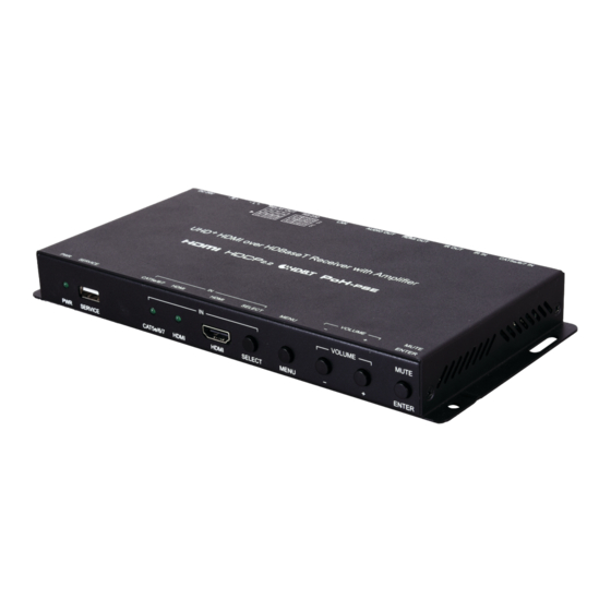
- Page 1 CH-2540RX HDMI over HDBaseT Receiver with Amplifier Operation Manual Operation Manual...
- Page 3 DISCLAIMERS The information in this manual has been carefully checked and is believed to be accurate. Cypress Technology assumes no responsibility for any infringements of patents or other rights of third parties which may result from its use. Cypress Technology assumes no responsibility for any inaccuracies that may be contained in this document.
- Page 4 SAFETY PRECAUTIONS Please read all instructions before attempting to unpack, install or operate this equipment and before connecting the power supply. Please keep the following in mind as you unpack and install this equipment: • Always follow basic safety precautions to reduce the risk of fire, electrical shock and injury to persons.
-
Page 5: Table Of Contents
CONTENTS 1. Introduction ............1 2. Applications ............. 2 3. Package Contents ........... 2 4. System Requirements ........2 5. Features............3 6. Operation Controls and Functions ....4 6.1 Front Panel ..........4 6.2 Rear Panel........... 5 6.3 Remote Control ........... 7 6.4 IR Cable Pinouts.......... -
Page 6: Introduction
1. INTRODUCTION This UHD HDMI over HDBaseT Receiver with Amplifier is a 2 by 1 switch with standard HDMI and HDBaseT inputs, an HDMI output, as well as both standard and amplified stereo audio outputs. This unit’s HDBaseT input can receive uncompressed high-definition 4K UHD (up to 10.2Gbps) video along with Ethernet, RS-232 and IR control over a single cable up to a distance of 100 meters while the HDMI input supports high bandwidth 4K UHD... -
Page 7: Applications
2. APPLICATIONS • Household entertainment sharing and control • Lecture room display and control • Showroom display and control • Meeting room presentation and control • Classroom display and control 3. PACKAGE CONTENTS • 1×UHD HDMI over HDBaseT Receiver with Amplifier •... -
Page 8: Features
5. FEATURES • HDMI 2.0 and HDBaseT 1.0 compatible • HDCP 1.x and 2.2 compliant • 1×HDMI and 1×HDBaseT inputs • 1×HDMI output • HDBaseT input supports resolutions up to 4K@60Hz (4:2:0, 8-bit) or 4K@30Hz (4:4:4, 8-bit). • HDMI input and output supports resolutions up to 4K UHD (18Gbps, 4K@60Hz 4:4:4, 8-bit) •... -
Page 9: Operation Controls And Functions
6. OPERATION CONTROLS AND FUNCTIONS 6.1 Front Panel VOLUME MUTE SERVICE CAT5e/6/7 HDMI HDMI SELECT MENU ENTER POWER LED: This LED will illuminate to indicate the unit is on and receiving power. SERVICE Port: This slot is reserved for firmware update use only. CAT5e/6/7 &... -
Page 10: Rear Panel
6.2 Rear Panel CAT5e/6/7 IN IR IN IR OUT HDMI OUT AUDIO OUT RS-232 RELAY OUT DC 24V CAT5e/6/7 IN Port: Connect to a compatible HDBaseT transmitter with a single Cat.5e/6/7 cable for reception of all data signals. PoH will also be supplied to a connected compatible PD transmitter. - Page 11 RS-232 CLI 4-pin Terminal Block: Connect to a PC, laptop, or serial controllable device with a 3-pin adapter cable for the extension of RS- 232 signals between both ends of the HDBaseT connection. Note: The 24 volt pins are included to provide power to a dedicated external control product and should NOT be used when connecting a standard RS-232 device.
-
Page 12: Remote Control
6.3 Remote Control HDBT Button: Press to switch to the HDBT HDMI HDBaseT input. HDMI Button: Press to switch to the HDMI MENU ENTER input. MENU Button: Press to enter the OSD menu, or to back out from menu items. ENTER Button: Press to confirm a selection within the OSD or to go deeper into a menu item. -
Page 13: Ir Cable Pinouts
6.4 IR Cable Pinouts IR Blaster IR Extender Cable Cable Power Infrared Infrared Power Not Used Ground 6.5 RS-232 Pinout and Defaults Serial Port Default Settings Baud Rate 19200 Data Bits Parity Bits None Stop Bits Flow Control None RS-232 Port 1 (CTL) RS-232 Port 2 (CLI) 4-pin Terminal Block 4-pin Terminal Block... -
Page 14: Osd Menu
6.6 OSD Menu All functions of this unit can be controlled by using the OSD (On Screen Display) which is activated by pressing the MENU button on the front of the unit. Use the + (PLUS), − (MINUS), and ENTER buttons to navigate the OSD menu. - Page 15 L/R AUDIO CONTROL 2ND LEVEL 3RD LEVEL 0~100 [30] Amp. Volume Amp. Mute Line Volume 0~100 [80] Line Mute Exit 1) Amp. Volume: Set the volume level for the amplified output. 2) Amp. Mute: Enable or disable muting the amplified audio output. 3) Line Volume: Set the volume level for the line audio output.
- Page 16 HDCP MODE 2ND LEVEL 3RD LEVEL In 1 Follow Display FOLLOW INPUT Disable In 2 Follow Display FOLLOW INPUT Disable Exit 1) In 1: Provides control over the HDCP behavior of the HDMI input. 2) In 2: Provides control over the HDCP behavior of the HDBaseT input. EDID MODE 2ND LEVEL 3RD LEVEL...
- Page 17 EDID MODE 2ND LEVEL 3RD LEVEL 4TH LEVEL FHD/PCM/2CH Appoint Mode In 1 FHD/PCM/MCH UHD/PCM/2CH UHD/PCM/MCH /PCM/2CH /PCM/MCH User 1 User 2 Sink FHD/PCM/2CH In 2 FHD/PCM/MCH UHD/PCM/2CH UHD/PCM/MCH /PCM/2CH /PCM/MCH User 1 User 2 Sink Exit 1) EDID Mode: Select how to assign EDIDs to the unit’s inputs. Selecting “Appoint Mode”...
- Page 18 OSD SETTING 2ND LEVEL 3RD LEVEL 0~100 [8] Timeout H. Position 0~100% [25%] 0~100% [25%] V. Position Transparency 0~7 [0] Exit 1) Timeout: Set the length of time to wait before automatically turning off the OSD menu if there is no user interaction. The timer is disabled when the value is set to 0.
- Page 19 SYSTEM SETTING 2ND LEVEL 3RD LEVEL Auto Switch Relay Output 1 Relay Output 2 Relay Output 3 Relay Output 4 Exit 1) Auto Switch: Enable or disable the unit’s auto switch feature. 2) Relay Output 1-4: Manually open or close Relays 1~4. Selecting “ON” closes the relay, selecting “OFF”...
-
Page 20: Webgui Control
6.7 WebGUI Control • Device Discovery Please obtain the “Device Discovery” software from your authorized dealer and save it in a directory where you can easily find it. Connect the unit and your PC/Laptop to the same active network and execute the “Device Discovery”... - Page 21 • WebGUI Overview After connecting to the WebGUI’s address in a web browser, the login screen will appear. Please enter the appropriate user name and password then click “Submit” to log in. Note: The default user name and password is “admin”. On the left side of the browser you will see the following menu tabs where all primary functions of the unit are controllable via the built in WebGUI.
-
Page 22: Video Switch Tab
6.7.1 Video Switch Tab This tab provides A/V routing control, HDCP management, auto switch control, A/V muting, and I/O renaming options. To assign a new video route, please click the Output button on the left and then click on the button of the preferred input port on the right. - Page 23 4) Remote TX (Compatible transmitters only): Buttons for selecting the input on the connected transmitter. Details about the input names and current sync/HDCP status are also displayed here. Clicking on the “Edit” icon ( ) opens up the Input Edit window. 5) Output Edit: Provides control over the name of the output.
-
Page 24: Audio Tab
6.7.2 Audio Tab This tab provides control over the volume level of the amplified and line level analog audio outputs. Note: HDMI audio output is always a direct pass-through from the selected source and is not affected by the controls on this tab. 1) Amplifier Volume (dB): Allows the adjustment of the amplified analog audio output’s volume level. -
Page 25: Relay Tab
6.7.3 Relay Tab This tab provides direct control over the unit’s 4 relay ports. 1) Relay Out Port 1~4: Manually open or close Relays 1~4. Selecting “ON” closes the relay, selecting “OFF” opens it. 6.7.4 OSD Setting Tab This tab provides control over the timeout, transparency, and position of the OSD menu displayed on the HDMI output. -
Page 26: Automation Tab
6.7.5 Automation Tab This tab provides control over the unit’s automatic control command broadcast behavior when any of the specified Automation Events occur. Automation commands can be sent to connected devices via IR, CEC, and RS-232. 1) Event: Use the dropdown to select the Automation Event to configure. Available Automation Events are: ■... - Page 27 ■ IR Command: Shows the IR command (in ASCII hex pairs) that will be sent when the specified Automation Event is activated. Click the “Edit” icon ( ) to learn the command from an IR remote. Click the “Test” button to send the command immediately. 3) CEC: Enable or disable sending a CEC command when the currently selected Automation Event is activated.
- Page 28 Note: RS-232 Automation commands will only be output over the “CTL” RS-232 port. ■ Delay: Set the length of time, in seconds, that the specified Automation Event must continue to be true before sending the defined RS-232 command. ■ Wait: Set the length of time, in seconds, to wait after this RS-232 Automation Event has been activated before ANY other Automation Event can be detected.
-
Page 29: Edid Tab
6.7.6 EDID Tab This tab provides control over the EDID settings of all inputs, including those on specially supported transmitters. This unit provides the option of six standard EDIDs, one sink sourced EDID and two user uploaded EDIDs that can be assigned to each input port individually. The names of the two user uploaded EDIDs can changed if desired. - Page 30 ■ Edit Name: Click the “Edit Name” button to open a window that allows changing the name of the User EDID. Click the “Save” button within the window to confirm the change. 2) Output EDID: ■ Download: To save the EDID from the connected display to your local PC, select the sink from the dropdown list then press the “Download”...
-
Page 31: Network Tab
is recommended to switch to one of the 6 default EDIDs for maximum compatibility. 3) Remote Tx EDID (Compatible transmitters only): Click on the transmitter’s button to open the EDID Table List window. Select the new EDID source to use, from the choices on the right, and the change will occur immediately on the transmitter. -
Page 32: System Tab
2) Web Login Account: The WebGUI admin password can be changed here. Please press “Save” after entering the old and new passwords to enact the change. Note: The default password is “admin”. 3) Web Login Timeout: Select the length of time to wait before logging the user out of the WebGUI due to inactivity. -
Page 33: Telnet Control
update file (*.bin format) located on your local PC. After selecting the file, click the “Upgrade” button to begin the firmware update process. After the upgrade is complete, the unit will reboot automatically. 5) Serial Number: Displays the unit’s serial number. 6.8 Telnet Control Before attempting to use Telnet control, please ensure that both the unit and the PC are connected to the same active networks. -
Page 34: Serial And Telnet Commands
6.9 Serial and Telnet Commands COMMAND Description and Parameters help Show the full command list. help N1 Show details about the specified command. N1 = {Command} ? Show the full command list. ? N1 Show details about the specified command. N1 = {Command} set in N1 name N2... - Page 35 COMMAND Description and Parameters get in N1 hactive Show the horizontal active pixel value of the specified input’s current video source. Available values for N1: [HDMI input] [HDBaseT input] get in N1 vactive Show the vertical active pixel value of the specified input’s current video source.
- Page 36 COMMAND Description and Parameters set out A name N1 Set the name of the HDMI output. N1 = {Name} [Output A name] get out A name Show the name of the HDMI output. set out A route N1 Route the specified input to the HDMI output. Available values for N1: [HDMI input] [HDBaseT input]...
- Page 37 COMMAND Description and Parameters set out auto mode N1 Set the auto switching behavior of the unit. Available values for N1: [Auto switch disabled] [Auto switch enabled] get out auto mode Show the current auto switching mode of the unit. set out A osd timeout N1...
- Page 38 COMMAND Description and Parameters get out A osd transparency Show the current transparency level of the OSD on the HDMI output. set edid N1 name N2 Set the name for the specified EDID. (Only User EDIDs may be renamed) N1 = 7~8 [EDID number] N2 = {Name} [16 characters maximum]...
- Page 39 COMMAND Description and Parameters set in N1 edid N2 Set the EDID to use on the specified input. Available values for N1: [HDMI input] [HDBaseT input] Available values for N2: [Internal EDID 1] [Internal EDID 2] [Internal EDID 3] [Internal EDID 4] [Internal EDID 5] [Internal EDID 6] [User EDID 1]...
- Page 40 COMMAND Description and Parameters get in N1 hdcp status Show the current HDCP status of the specified input. Available values for N1: [HDMI input] [HDBaseT input] Possible response values: [HDCP off] [HDCP 1.x] [HDCP 2.2] set in N1 hdcp mode N2 Set the HDCP behavior of the specified input.
- Page 41 COMMAND Description and Parameters set audio out N1 volume N2 Set the volume level of the specified output’s audio. Available values for N1: [Amplified audio output] [Line audio output] N2 = 0~100 [Volume level] get audio out N1 volume Show the current volume level of the specified output’s audio. Available values for N1: [Amplified audio output] [Line audio output]...
- Page 42 COMMAND Description and Parameters get audio out N1 mute Show the current mute state of the specified output. Available values for N1: [Amplified audio output] [Line audio output] set audio out arc N1 Enable or disable ARC support on the HDMI output. Available values for N1: [ARC disabled] [ARC enabled]...
- Page 43 COMMAND Description and Parameters get netmask Show the unit’s current netmask. set gateway N1 Set the unit’s static gateway address. N1 = X.X.X.X [X = 0~255, gateway address] get gateway Show the unit’s current gateway address. set webgui password N1 Set the WebGUI login password.
- Page 44 COMMAND Description and Parameters get telnet port Show the unit’s current Telnet access port. set automation event N1 cec A N2 Enable or disable the specified Automation Event’s CEC response. Available values for N1: [Power on] [Output A source active] [Output A source lost] Available values for N2: [Disable]...
- Page 45 COMMAND Description and Parameters get automation event N1 cec A delay Show the delay time for the specified Automation Event’s CEC response. Available values for N1: [Power on] [Output A source active] [Output A source lost] set automation event N1 cec A wait N2 Set the length of time to wait after an Automation Event’s CEC response has been activated before ANY other Automation Event can be detected.
- Page 46 COMMAND Description and Parameters set automation event N1 uart A N2 Enable or disable the specified Automation Event’s RS-232 response. Available values for N1: [Power on] [Output A source active] [Output A source lost] Available values for N2: [Disable] [Enable] get automation event N1 uart A...
- Page 47 COMMAND Description and Parameters get automation event N1 uart A delay Show the delay time for the specified Automation Event’s RS-232 response. Available values for N1: [Power on] [Output A source active] [Output A source lost] set automation event N1 uart A wait N2 Set the length of time to wait after an Automation Event’s RS-232 response has been activated before ANY other Automation Event can be detected.
- Page 48 COMMAND Description and Parameters get automation event N1 uart A command Show the RS-232 command string to be sent when the specified Auto- mation Event is activated. set automation event N1 ir A N2 Enable or disable the specified Automation Event’s IR response. Available values for N1: [Power on] [Output A source active]...
- Page 49 COMMAND Description and Parameters get automation event N1 ir A delay Show the delay time for the specified Automation Event’s IR response. Available values for N1: [Power on] [Output A source active] [Output A source lost] set automation event N1 ir A wait N2 Set the length of time to wait after an Automation Event’s IR response has been activated before ANY other Automation Event can be detected.
- Page 50 COMMAND Description and Parameters set uart 1 baudrate N1 Set the baud rate of the CTL RS-232 port. Available values for N1: 4800 [4800 baud] 9600 [9600 baud] 19200 [19200 baud] 38400 [38400 baud] 57600 [57600 baud] 115200 [115200 baud] get uart 1 baudrate...
- Page 51 COMMAND Description and Parameters set ir in channel N1 Set the channel for the IR input to use. Available values for N1: [Channel 0] [Channel 1] [Channel 2] [Channel 3] get ir in channel Show the current channel used by the IR input. set ir in custom code N1...
- Page 52 COMMAND Description and Parameters update mcu Initiate firmware update via the USB port. Note: Commands will not be executed unless followed by a carriage return. Commands are not case-sensitive.
-
Page 53: Connection Diagram
7. CONNECTION DIAGRAM DVD/Blu-ray Player RS-232 Equipped Remote PC/Laptop Control RS-232 Controlled Projector Router 60° IR Out 1.5m Headphones 60° Cable RS-232 Powered Projector Screen RS-232 IN POWER STD UPDATE LINK BLASTER HDMI IN EXTENDER HDMI In Stereo Output RS-232 Relay Output CAT5e/6/7... -
Page 54: Specifications
8. SPECIFICATIONS 8.1 Technical Specifications HDMI Bandwidth 18Gbps HDBaseT Bandwidth 10.2Gbps Input Ports 1×HDMI (Type-A) 1×HDBaseT (RJ-45) Output Ports 1×HDMI (Type-A) 1×Stereo Audio (3.5mm) 1×Stereo Audio (2×2-pin Term. Block) Pass-through Ports 1×IR Extender (3.5mm) 1×IR Blaster (3.5mm) 1×RS-232 (4-pin Terminal Block) 4×Power Relay (2-pin Terminal Block) Pass-through/Control Port 1×LAN (RJ-45) -
Page 55: Video Specifications
8.2 Video Specifications Input Output Supported Resolutions (Hz) HDMI HDBaseT HDMI 720×400p@70/85 640×480p@60/72/75/85 720×480i@60 720×480p@60 720×576i@50 720×576p@50 800×600p@56/60/72/75/85 848×480p@60 ... - Page 56 Input Output Supported Resolutions (Hz) HDMI HDBaseT HDMI 2560×1440p@60RB 2560×1600p@60RB 2048×1080p@24/25/30 2048×1080p@50/60 3840×2160p@24/25/30 3840×2160p@50/60 (4:2:0) 3840×2160p@24, HDR10 3840×2160p@50/60 (4:2:0), ...
-
Page 57: Audio Specifications
8.3 Audio Specifications 8.3.1 Digital Audio HDMI Input / Output LPCM Max Channels 8 Channels Sampling Rate (kHz) 32, 44.1, 48, 88.2, 96, 176.4, 192 Bitstream Supported Formats Standard & High-Definition HDBaseT Input LPCM Max Channels 8 Channels Sampling Rate (kHz) 32, 44.1, 48, 88.2, 96, 176.4, 192 Bitstream Supported Formats... -
Page 58: Analog Audio
8.3.2 Analog Audio Analog Output (3.5mm) Max Audio Level 2Vrms THD+N < −80dB@0dBFS 1kHz (A-wt) > 110dB@0dBFS Frequency Response < ±1dB@20Hz~20kHz Crosstalk < −88dB@10kHz Impedance 499Ω Type Unbalanced Analog Output (2-pin Terminal Block Pair) Max Audio Level 20W+20W THD+N < −62dB@0dBFS 1kHz (A-wt) >... -
Page 59: Cable Specifications
8.4 Cable Specifications 1080p 4K30 4K60 (4:4:4) (4:4:4) Cable Length 8-bit 12-bit 8-bit 8-bit High Speed HDMI Cable HDMI Input HDMI Output Ethernet Cable Cat.5e/6 100m Cat.6A/7 100m 100m Bandwidth Category Examples: • 1080p (FHD Video) - Up to 1080p@60Hz, 12-bit color - Data rates lower than 5.3Gbps or below 225MHz TMDS clock •... -
Page 60: Hdbaset Features
8.5 HDBaseT Features HDBaseT Feature Set Receiver Video & Audio Extension Supported LAN Extension Supported Send power to Transmitter Supported (PoH) Accept power from Transmitter Unsupported IR Extension Supported RS-232 Extension Supported USB 2.0 Extension Unsupported... -
Page 61: Acronyms
9. ACRONYMS ACRONYM COMPLETE TERM Audio Return Channel ASCII American Standard Code for Information Interchange Cat.5e Enhanced Category 5 cable Cat.6 Category 6 cable Cat.6A Augmented Category 6 cable Cat.7 Category 7 cable Consumer Electronics Control Command-Line Interface Digital-to-Analog Converter Decibel DHCP Dynamic Host Configuration Protocol... - Page 62 ACRONYM COMPLETE TERM Powered Device Power over HDBaseT Power Sourcing Equipment Signal-to-Noise Ratio Transmission Control Protocol THD+N Total Harmonic Distortion plus Noise 4K UHD 4K Ultra-High-Definition (10.2Gbps max) 4K UHD 4K Ultra-High-Definition (18Gbps max) Universal Serial Bus Video Graphics Array WUXGA (RB) Widescreen Ultra Extended Graphics Array (Reduced Blanking)
- Page 64 CYPRESS TECHNOLOGY CO., LTD. www.cypress.com.tw...
Need help?
Do you have a question about the CH-2540RX and is the answer not in the manual?
Questions and answers