
Related Manuals for CYP CH-2527TXV


Summary of Contents for CYP CH-2527TXV
- Page 1 CH-2527TXV & CH-2527RXV 4K UHD+ HDMI w/HDR over HDBaseT Transmitter (PD) & Receiver (PSE) Operation Manual Operation Manual...
- Page 3 DISCLAIMERS The information in this manual has been carefully checked and is believed to be accurate. Cypress Technology assumes no responsibility for any infringements of patents or other rights of third parties which may result from its use. Cypress Technology assumes no responsibility for any inaccuracies that may be contained in this document.
- Page 4 SAFETY PRECAUTIONS Please read all instructions before attempting to unpack, install or operate this equipment and before connecting the power supply. Please keep the following in mind as you unpack and install this equipment: • Always follow basic safety precautions to reduce the risk of fire, electrical shock and injury to persons.
-
Page 5: Table Of Contents
CONTENTS 1. Introduction ............1 2. Applications .............1 3. Package Contents ..........1 4. System Requirements ........2 5. Features ............3 6. Operation Controls and Functions ....4 6.1 Transmitter's Front and Rear Panels ..4 6.2 Receiver's Front and Rear Panels .... 6 6.5 IR Cable Pinouts ........ -
Page 6: Introduction
1. INTRODUCTION This transmitter and receiver set is a great solution for extending UHD video and audio as well as Ethernet and control via a single run of Cat.5e/6/7 cable over distances up to 100 meters. This extender set complies with the advanced HDCP 2.2 and HDMI 2.0 standards, as well as supporting the legacy HDCP 1.x and HDMI 1.x standards. -
Page 7: System Requirements
4. SYSTEM REQUIREMENTS • HDMI source equipment such as media players, video game consoles or set-top boxes. • HDMI receiving equipment such as HDTVs, monitors or audio amplifiers. • The use of "Premium High Speed" HDMI cables, and industry standard Cat.6, Cat.6a or Cat.7, is highly recommended. -
Page 8: Features
5. FEATURES • HDMI with HDR, 3D & 4K@60Hz support, DVI 1.0 compatible • HDCP 2.2 and HDCP 1.x compliant • Supports up to 4K UHD (18Gbps, 4K@50/60Hz 4:4:4, 8-bit) video input and output • Supports Deep Color input and output up to 12-bit •... -
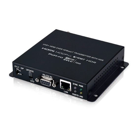
Page 9: Operation Controls And Functions
6. OPERATION CONTROLS AND FUNCTIONS 6.1 Transmitter's Front and Rear Panels AVLC UPDATE BLASTER EXTENDER CAT5e/6/7 OUT HDMI IN HQ/STD AVLC HQ/STD Switch: This switch allows the user to select which compression mode to use when AVLC is active. HQ (High Quality) mode uses the least amount of compression and provides the highest possible visual quality (perceptually identical to the original). - Page 10 SYNC LED: This LED will illuminate when a live input source is detected. HQ/STD LED: This LED will illuminate whenever the AVLC function is active. A green LED indicates that AVLC is in HQ (High Quality) mode. A red LED indicates that AVLC is in STD (Standard) mode. POWER LED: This LED will illuminate to indicate the unit is on and receiving power.
-
Page 11: Receiver's Front And Rear Panels
6.2 Receiver's Front and Rear Panels UPDATE HQ/STD DC 48V BLASTER EXTENDER HDMI OUT ISP Pinhole: This button is reserved for factory use only. UPDATE Switch: This switch is reserved for factory use only. The default setting is “STD”. RS-232 OUT Port: Connect to a PC, laptop, or serial controllable device for the extension of RS-232 signals between both ends of the HDBaseT connection. - Page 12 DC 48V Port: Plug the 48V DC power adapter into this port and connect it to an AC wall outlet for power. IR2 BLASTER Port: Connect to an IR Blaster to transmit IR signals from the other end of the HDBaseT connection to devices within direct line-of-sight of the IR Blaster.
-
Page 13: Ir Cable Pinouts
6.5 IR Cable Pinouts IR Blaster IR Extender Cable Cable Power Infrared Infrared Power Not Used Ground 6.6 RS-232 Pinout DE-9 Female Port DE-9 Male Port... -
Page 14: Connection Diagram
7. CONNECTION DIAGRAM DVD/Blu-ray Player HDMI IR In & Out Input Router 1.5m 60° 60° RS-232 RS-232 Equipped PC/Laptop AVLC UPDATE HQ/STD BLASTER EXTENDER CAT5e/6/7 OUT HDMI IN Cat.5e/6/7 Cable Power Supply DC 48V BLASTER EXTENDER HDMI OUT UPDATE HQ/STD 60°... -
Page 15: Specifications
8. SPECIFICATIONS 8.1 Technical Specifications (Transmitter) HDMI Bandwidth 600MHz/18Gbps HDBaseT Bandwidth 340MHz/10.2Gbps Input Ports 1×HDMI (Type-A) Output Ports 1×HDBaseT (RJ-45) Pass-through Ports 1×IR Extender (3.5mm) 1×IR Blaster (3.5mm) 1×RS-232 (DE-9) 1×LAN (RJ-45) IR Frequency 30 – 50kHz (30 – 60kHz under ideal conditions) Baud Rate Up to 115200 Power Supply... - Page 16 8.2 Technical Specifications (Receiver) HDMI Bandwidth 600MHz/18Gbps HDBaseT Bandwidth 340Hz/10.2Gbps Input Port 1×HDBaseT (RJ-45) Output Port 1×HDMI (Type-A) Pass-through Ports 1×IR Extender (3.5mm) 1×IR Blaster (3.5mm) 1×RS-232 (DE-9) 1×LAN (RJ-45) IR Frequency 30 - 50kHz (30 - 60kHz under ideal conditions) Baud Rate Up to 115200 Power Supply...
-
Page 17: Video Specifications
8.3 Video Specifications Input Output Supported Resolutions (Hz) HDMI HDBT HDBT HDMI 720×400p@70/85 640×480p@60/72/75/85 720×480i@60 720×480p@60 720×576i@50 720×576p@50 ... -
Page 18: Audio Specifications
Input Output Supported Resolutions (Hz) HDMI HDBT HDBT HDMI 1920×1200p@60RB 2048×1080p@24/25/30 2048×1080p@50/60 2560×1440p@60RB 2560×1600p@60RB 3840×2160p@24/25/30 3840×2160p@50/60 (4:2:0) ... -
Page 19: Cable Specifications
8.5 Cable Specifications 1080p 4K30 4K60 (4:4:4) (4:4:4) Cable Length 8-bit 12-bit 8-bit 8-bit High Speed HDMI Cable HDMI Input HDMI Output Ethernet Cable Cat.5e/6 100m Cat.6a/7 100m 100m • 1080p (FHD Video) - Up to 1080p@60Hz, 12-bit color - Data rates lower than 5.3Gbps or below 225MHz TMDS clock •... -
Page 20: Hdbaset Features
8.6 HDBaseT Features HDBaseT Feature Set Transmitter Video & Audio Supported LAN Pass-through Supported Send power to Receiver Unsupported Accept power from Receiver Supported IR Pass-through Supported RS-232 Pass-through Supported HDBaseT Feature Set Receiver Video & Audio Supported LAN Pass-through Supported Send power to Transmitter Supported... -
Page 21: Acronyms
9. ACRONYMS ACRONYM COMPLETE TERM Audio/Video AVLC Adaptive Visually Lossless Compression Cat.5e Enhanced Category 5 cable Cat.6 Category 6 cable Cat.6a Augmented Category 6 cable Cat.7 Category 7 cable Consumer Electronics Control Digital Visual Interface EDID Extended Display Identification Data High-Definition HDBT HDBaseT... - Page 22 ACRONYM COMPLETE TERM UHD+ Ultra-High-Definition Plus UHDTV Ultra-High-Definition Television Video Graphics Array WUXGA (RB) Widescreen Ultra Extended Graphics Array (Reduced Blanking) Extended Graphics Array...
- Page 24 CYPRESS TECHNOLOGY CO., LTD. www.cypress.com.tw...
Need help?
Do you have a question about the CH-2527TXV and is the answer not in the manual?
Questions and answers