
Related Manuals for CYP CH-352RX


Summary of Contents for CYP CH-352RX
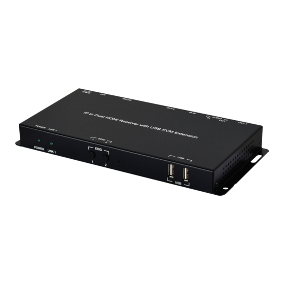
- Page 1 CH-352RX IP to Dual HDMI Receiver with USB KVM Extension Operation Manual Operation Manual...
- Page 3 DISCLAIMERS The information in this manual has been carefully checked and is believed to be accurate. Cypress Technology assumes no responsibility for any infringements of patents or other rights of third parties which may result from its use. Cypress Technology assumes no responsibility for any inaccuracies that may be contained in this document.
- Page 4 SAFETY PRECAUTIONS Please read all instructions before attempting to unpack, install or operate this equipment and before connecting the power supply. Please keep the following in mind as you unpack and install this equipment: • Always follow basic safety precautions to reduce the risk of fire, electrical shock and injury to persons.
-
Page 5: Table Of Contents
CONTENTS 1. Introduction ............1 2. Applications ............. 1 3. Package Contents ........... 1 4. System Requirements ........2 5. Features............2 6. Operation Controls and Functions ....3 6.1 Front Panel ..........3 6.2 Rear Panel........... 4 6.3 IR Cable Pinouts.......... 5 6.4 RS-232 Pinout and Defaults ...... -
Page 6: Introduction
1. INTRODUCTION This IP to Dual HDMI Receiver solution is designed to receive a pair of independently extended HDMI sources via a standard Gigabit Ethernet network connection and output them via dual HDMI outputs. Both HDMI outputs provide support for received resolutions up to 1920x1200@60Hz along with many audio formats including 8 channel LPCM and standard Bitstream. -
Page 7: System Requirements
4. SYSTEM REQUIREMENTS • HDMI receiving equipment such as HDTVs, monitors or audio amplifiers. • A compatible dual-AVoIP transmitter • Analog audio receiving equipment such as headphones, audio amplifiers or powered speakers. • A Gigabit Ethernet network switch with jumbo frame support is required. (8K jumbo frames are strongly recommended) •... -
Page 8: Operation Controls And Functions
6. OPERATION CONTROLS AND FUNCTIONS 6.1 Front Panel EDID POWER LINK 1 POWER LED: This LED will flash while the unit is powering on and will illuminate solidly once it is ready to be used. LINK 1 LED: If the unit has no network connection this LED will not illuminate. -
Page 9: Rear Panel
6.2 Rear Panel AUDIO DC 5V OUT 1 IR IN OUT 2 RS-232 OUT 1 Port: Connect to an HDMI TV, monitor, or amplifier for digital video and audio output. Note: The source will always be the device connected to HDMI input 1 on the connected transmitter. -
Page 10: Ir Cable Pinouts
6.3 IR Cable Pinouts IR Extender Cable Infrared Power Ground 6.4 RS-232 Pinout and Defaults Serial Port Default Settings Baud Rate 115200 Data Bits DE-9 Male Port Parity Bits None Stop Bits Flow Control None... -
Page 11: Webgui Control
6.5 WebGUI Control • Device Discovery Please obtain the “Device Discovery” software from your authorized dealer and save it in a directory where you can easily find it. Connect the unit and your PC/Laptop to the same active network and execute the “Device Discovery”... - Page 12 • WebGUI Overview Each unit contains 2 independent AVoIP receivers, and each of those is controlled by their own WebGUI interface which may be accessed by opening a standard web browser on a PC and typing in the IP address of the unit you wish to connect to.
-
Page 13: System Tab
6.5.1 System Tab The System tab contains four windows that provide access to firmware version information, a firmware update interface, utilities for rebooting and resetting the unit, Telnet command entry, and a variety of statistics and information about the operational state of the unit. 1) Version Information: This window displays detailed information about this receiver’s current firmware version. - Page 14 3) Utilities Window: The Utilities window provides control over some system-level functions. ■ Factory Default: Users can reset this receiver back to the factory defaults by clicking this button. ■ Reboot: The unit may be rebooted (without resetting settings) by pressing this button.
- Page 15 4) Statistics Window: The Statistics window shows all available information about the operational status of the unit, including current Host ID Name, SN, Ethernet information, MAC address, broadcast reception mode, link status and link mode.
-
Page 16: Network Tab
6.5.2 Network Tab The Network tab provides control over this receiver’s IP configuration. Changes made to the network settings will require a reboot of the unit. After clicking on “Apply” please follow the reboot instructions in the WebGUI. Note: If the IP address is changed then the IP address required for WebGUI and Telnet access will also change accordingly. -
Page 17: Functions Tab
Note: The default network setting for this unit is “Auto IP”. If the unit is set to “DHCP” but no DHCP server can be found, the IP mode will temporarily switch to “Auto IP” until the unit is rebooted. ■ Find Your Device: Selecting “Show Me” will cause the unit to immediately begin flashing the LEDs on the front of the unit to make it easy to find. - Page 18 ■ Enable Video over IP: Unchecking this checkbox will disable the AVoIP stream completely. This option should always remain checked unless troubleshooting is being performed. ■ Video Loss Options: Use the drop down to set the length of time to wait for a lost source to return before showing the “Link Lost”...
-
Page 19: Telnet Control
2) USB over IP (Receiver 1 Only): This section provides control over the USB over IP extension functionality. ■ Enable USB over IP: Unchecking this checkbox will completely disable support for USB streaming to this unit. This option should generally remain checked, but, if USB support is not required, disabling this feature can save some bandwidth. -
Page 20: Telnet Commands
6.7 Telnet Commands COMMAND Description and Parameters help Show the full command list. help N1 Show details about the specified command. N1 = {Command} get_hardware_version Show the receiver's current hardware version. get_firmware_version Show the receiver's current firmware version. set_device_name N1 Set the receiver’s device name. - Page 21 COMMAND Description and Parameters set_ip_mode N1 Set the IP address assignment mode. Available values for N1: [Static IP Mode] [DHCP Mode] [Auto IP Mode] get_ip_mode Show the current IP address assignment mode. set_ip_address N1 Set the receiver's static IP address. N1 = X.X.X.X [X = 0~255, IP address] get_ip_address...
- Page 22 COMMAND Description and Parameters get_jumbo_mtu Show the receiver’s current jumbo frame MTU support status. set_showme N1 Enable/Disable the receiver’s discovery “Show Me” feature. Available values for N1: [Disabled] [Enabled] get_showme Show the current state of the receiver’s “Show Me” feature.
- Page 23 COMMAND Description and Parameters set_output_res Set the receiver’s output scaling mode. Available values for N1: [640x480 60Hz] [800x600 60Hz] [1024x768 60Hz] [1280x768 60Hz] [1280x800 60Hz] [1280x1024 60Hz] [1360x768 60Hz] [1366x768 60Hz] [1440x900 60Hz] [1400x1050 60Hz] [1600x900 60Hz] [1600x1200 60Hz] [1680x1050 60Hz] [1920x1200 60Hz] [Bypass] [Auto-Detect]...
- Page 24 COMMAND Description and Parameters set_serial_allow Enable/disable serial bypass support. Available values for N1: [Disable] [Enable] Note: Valid on Receiver 1 only. get_serial_allow Show the current serial bypass support state. Note: Valid on Receiver 1 only. set_serial_baud N1 Set the serial baud rate. Available values for N1: [300 baud] [600 baud]...
- Page 25 COMMAND Description and Parameters set_serial_bits N1 Set the number of serial data bits. Available values for N1: [5 bits] [6 bits] [7 bits] [8 bits] Note: Valid on Receiver 1 only. get_serial_bits Show the current number of serial data bits. Note: Valid on Receiver 1 only.
- Page 26 COMMAND Description and Parameters a N1 Set the audio input source selection for Receiver 1. Available values for N1: [Transmitter 1’s HDMI 1 audio] [Transmitter 1’s Line In audio] AUTO [Auto select] Note: Valid on Receiver 1 only. get_A Show Receiver 1’s current audio input source selection. Note: Valid on Receiver 1 only.
-
Page 27: Connection Diagram
7. CONNECTION DIAGRAM Blu-ray Player 1.5m 60° IR Output POWER LINK 1 AUDIO DC 5V IN 1 IN 2 RS-232 HDMI Input Analog Stereo Input HDMI Input USB Peripherals EDID POWER LINK 1 AUDIO DC 5V OUT 1 IR IN OUT 2 RS-232 HDMI... -
Page 28: Specifications
8. SPECIFICATIONS 8.1 Technical Specifications HDMI Bandwidth 6.75Gbps Input Port 1×Analog Mono (3.5mm) Input/Control Port 1×LAN (RJ-45) Output Ports 2×HDMI (Type-A) 1×Analog Stereo (3.5mm) Pass-through Ports 1×IR Extender (3.5mm) 1×RS-232 (DE-9) 2×USB (Type-A) IR Frequency 30 ~ 50kHz (30 ~ 60kHz under ideal conditions) Baud Rate Up to 115200 Power Supply... -
Page 29: Video Specifications
8.2 VIDEO SPECIFICATIONS Input Output Supported Resolutions (Hz) Streaming HDMI 720×400p@70/85 640×480p@60/72/75/85 720×480i@60 720×480p@60 720×576i@50 720×576p@50 800×600p@56/60/72/75/85 848×480p@60 1024×768p@60/70/75/85 1152×864p@75 1280×720p@50/60 ... - Page 30 Input Output Supported Resolutions (Hz) Streaming HDMI 2560×1440p@60RB 2560×1600p@60RB 2048×1080p@24/25/30 2048×1080p@50/60 3840×2160p@24/25/30 3840×2160p@50/60 (4:2:0) 3840×2160p@24, HDR10 3840×2160p@50/60 (4:2:0), HDR10 3840×2160p@50/60 4096×2160p@24/25/30 ...
-
Page 31: Audio Specifications
8.3 Audio Specifications 8.3.1 Digital Audio Streaming Input / HDMI Output LPCM Max Channels 8 Channels Sampling Rate (kHz) 32, 44.1, 48, 88.2, 96, 176.4, 192 Bitstream Supported Formats Standard 8.3.2 Analog Audio Analog Input Max Audio Level 2Vrms Impedance 10kΩ... -
Page 32: Avoip Audio Availability (Auto Mode)
8.3.3 AVoIP Audio Availability (Auto Mode) Connected Audio Sources Audio Source Output HDMI 1 IN LINE IN LINE IN HDMI 1 LINE OUT LINE OUT (TX) (TX) (RX) OUT (RX) (TX) (RX) ● ● ● ■ ■ ■ ● ■... -
Page 33: Cable Specifications
8.4 Cable Specifications 1080p 4K30 4K60 (4:4:4) (4:4:4) 8-bit 12-bit 8-bit 8-bit Cable Length High Speed HDMI Cable HDMI Input Ethernet Cable Cat.5e/6 100m Cat.6A/7 100m Bandwidth Category Examples: • 1080p (FHD Video) - Up to 1080p@60Hz, 12-bit color - Data rates lower than 5.3Gbps or below 225MHz TMDS clock •... -
Page 34: Acronyms
9. ACRONYMS ACRONYM COMPLETE TERM Analog-to-Digital Converter Audio/Video AVoIP Audio/Video over IP Cat.5e Enhanced Category 5 cable Cat.6 Category 6 cable Cat.6A Augmented Category 6 cable Cat.7 Category 7 cable Command-Line Interface Digital-to-Analog Converter Decibel DHCP Dynamic Host Configuration Protocol Digital Visual Interface EDID Extended Display Identification Data... - Page 35 ACRONYM COMPLETE TERM MJPEG Motion JPEG Megahertz On-Screen Display Signal-to-Noise Ratio Transmission Control Protocol THD+N Total Harmonic Distortion plus Noise 4K UHD 4K Ultra-High-Definition (10.2Gbps max) 4K UHD 4K Ultra-High-Definition (18Gbps max) Universal Serial Bus Video Graphics Array VLAN Virtual LAN VoIP Video over IP WUXGA (RB)
- Page 36 CYPRESS TECHNOLOGY CO., LTD. www.cypress.com.tw...
Need help?
Do you have a question about the CH-352RX and is the answer not in the manual?
Questions and answers