
Related Manuals for Fluidwell F040-U


Summary of Contents for Fluidwell F040-U
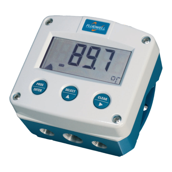
- Page 1 F040-U TEMPERATURE INDICATOR Signal input sensor: 0-10V Options: Intrinsically Safe. F-Series - Field mounted indicators for safe and hazardous areas. More info: www.fluidwell.com/fseries...
-
Page 2: Safety Instructions
This unit must be installed in accordance with the EMC guidelines (Electro Magnetic Compatibility). Do connect a proper grounding to the aluminum casing as indicated if the F040-U has been supplied with the 115-230V AC power-supply type PM. The green / yellow wire between the back-casing and removable terminal-block may never be removed. -
Page 3: About The Operation Manual
This operation manual describes the standard unit as well as most of the options available. For additional information, please contact your supplier. A hazardous situation may occur if the F040-U is not used for the purpose it was designed for or is used incorrectly. Please carefully note the information in this operating manual indicated by the pictograms: A "warning"... -
Page 4: Table Of Contents
..............................2 Safety rules and precautionary measures ....................... 2 About the operation manual ..........................3 Contents manual .............................. 4 Introduction ..........................5 1.1. System description of the F040-U..................5 Operational ..........................6 2.1. General ..........................6 2.2. Control panel .......................... 6 2.3. -
Page 5: Introduction
Fig. 1: Typical application for the F040-U. Configuration of the unit The F040-U has been designed to be implemented in many types of applications. For that reason, a SETUP-level is available to configure your F040-U according to your specific requirements. -
Page 6: Operational
Take careful notice of the " Safety rules, instructions and precautionary measures " in the front of this manual. This chapter describes the daily use of the F040-U. This instruction is meant for users / operators. 2.2. CONTROL PANEL The following keys are available: Fig. -
Page 7: Operator Information And Functions
SETUP-settings. The signal generated by the connected sensor is measured by the F040-U in the background, whichever screen refresh rate setting is chosen. After pressing a key, the display will be updated very quickly during a 30 second period, after which it will slow-down again. -
Page 8: Configuration
Operating Manual before carrying out its instructions. The F040-U may only be operated by personnel who are authorized and trained by the operator of the facility. All instructions in this manual are to be observed. - Page 9 Page 9 Matrix structure SETUP-level: SCROLLING THROUGH SETUP-LEVEL Selection of function-group and function: SETUP is divided into several function groups and functions. Each function has a unique number, which is displayed below the word "SETUP" at the bottom of the display. The number is a combination of two figures. The first figure indicates the function-group and the second figure the sub-function.
- Page 10 Page 10 To change or select a value: To change a value, use to select the digits and to increase that value. If the new value is invalid, the increase sign or decrease-sign will be displayed while you are programming.
-
Page 11: Overview Functions Setup Level
CUT-OFF 0.0 - 99.9% CALIBRATE LOW default - calibrate - calibrate set CALIBRATE HIGH default - calibrate - calibrate set OTHERS TYPE / MODEL F040-U SOFTWARE VERSION 03.xx.xx SERIAL NO. xxxxxxx PASS CODE 0000 - 9999 TAGNUMBER 0000000 - 9999999 3.2.3. -
Page 12: Display
When used with the internal battery option, the user can expect reliable measurement over a long period of time. The F040-U has several smart power management functions to extend the battery life time significantly. Two of these functions can be set:... -
Page 13: Sensor
The analog output signal of a sensor does mirror the actual temperature. FILTER This signal is measured several times a second by the F040-U. The value measured is a "snap-shot" of the real temperature as it will be fluctuating. With the help of this digital filter a stable and accurate reading can be obtained while the filter temperature can be set to a desired value. -
Page 14: Sensor (Continued)
For support and maintenance it is important to have information about the TYPE OF MODEL characteristics of the F040-U. Your supplier will ask for this information in the case of a serious breakdown or to assess the suitability of your model for upgrade considerations. -
Page 15: Installation
Operating Manual before carrying out its instructions. The F040-U may only be operated by personnel who are authorized and trained by the operator of the facility. All instructions in this manual are to be observed. -
Page 16: Dimensions- Enclosure
Page 16 4.3. DIMENSIONS- ENCLOSURE Aluminum enclosures: 75 mm (2.95") 112 mm (4.40") 130 mm (5.12") 12mm 12mm 30mm 30mm 24mm 24mm M20 x 1,5 6 x M12 36mm 36mm 30mm 30mm M16 x 1,5 M16 x 1,5 1/2"NPT M20 x 1,5 0.12"... - Page 17 Page 17 GRP enclosures: 75 mm (2.95") 112 mm (4.40") 130 mm (5.12") HK back box: (flat bottom) 75 mm (2.95") 118 mm (4.65”) 25mm 25mm D=20mm D=20mm 12mm 12mm 30mm 30mm 24mm 24mm D=12mm D=16mm D=16mm D=20mm 36mm 36mm 0.12”...
-
Page 18: Installing The Hardware
This unit must be installed in accordance with the EMC guidelines (Electro Magnetic Compatibility). Do ground the aluminum casing properly as indicated, if the F040-U has been supplied with the 115-230V AC power-supply type PM. The green / yellow wire between the back- casing and removable terminal-block may never be removed. - Page 19 REMARKS: TERMINAL CONNECTORS: Terminals 1-2; Sensor input type U - 0-10V: The F040-U requires a 0-10V sensor signal which will be processed 4 times a second with a 16 bits accuracy. The input is not isolated. The screen of the signal wire must be connected to the common ground terminal.
-
Page 20: Terminal Connectors With Power Supply - Type : Pf / Pm
PF / PM 0-10V INPUT SIGNAL Fig. 9: Overview of terminal connectors F040-U-(PF / PM) and options. SENSOR SUPPLY Type PF-PM: Sensor supply: 8.2V, 12V or 24 V: With this option, a real power supply for the sensor is available. The sensor can be powered with 8.2, 12 or 24 V DC (max. - Page 21 400mA@24V DC. Terminals 5-7; Flowmeter input: The F040-U requires a 0-10V flowmeter signal which will be processed 4 times a second with a 16 bit accuracy. The input is not isolated. The screen of the signal wire must be connected to the common ground terminal 5.
-
Page 22: Intrinsically Safe Applications
Safety Instructions Certificates, safety values, control drawing and declaration of compliance can be found in the document named: “Fluidwell F0..-U-XI - Documentation for Intrinsic Safety”. For installation under ATEX directive: this intrinsically safe device must be installed in accordance with the Atex directive 94/9/EC and the product certificate KEMA 05ATEX1168 X. -
Page 23: Terminal Connectors Intrinsically Safe Applications
CSA Certificate nr: CSA.08.2059461 – FM Project ID: 3033306 Made in Veghel, The Netherlands by Fluidwell bv Fig. 12: Label information Intrinsically Safe application. 5.2. TERMINAL CONNECTORS INTRINSICALLY SAFE APPLICATIONS: Terminal connectors F040-U-(PC / PD / PL / PX)-XI-(ZB): SENSOR SIGNAL POWER SUPPLY SENSOR POWER SUPPLY... -
Page 24: Configuration Example Intrinsically Safe Applications
Page 24 5.3. CONFIGURATION EXAMPLE INTRINSICALLY SAFE APPLICATIONS: Configuration example Configuration example IIA - IIB and IIC application - F040-U-PD-XI-ZB HAZARDOUS AREA SAFE AREA TERMINAL CONNECTORS F0-series = max. 30 V Power supply Supply backlight = max. 200 mA Backlight option: type ZB For example = max. - Page 25 Page 25 5.4. BATTERY REPLACEMENT INSTRUCTIONS FW-LiBAT-001 - INST001 Fig. 15: Battery replacement instructions Intrinsically Safe Battery. HF040UEN_v0403_03 Atex_IECEx_CSA_FM...
-
Page 26: Maintenance
Operating Manual before carrying out its instructions. The F040-U may only be operated by personnel who are authorized and trained by the operator of the facility. All instructions in this manual are to be observed. -
Page 27: Appendix A: Technical Specification
Page 27 APPENDIX A: TECHNICAL SPECIFICATION GENERAL Display Type High intensity reflective numeric and alphanumeric LCD, UV-resistant. Digits 5 ½ 26mm (1") and eleven 8mm (0.31"). Various symbols and measuring units. Pie graph 10 segment range indication in relation to its measuring range 0-100% Refresh rate User definable: 8 times/sec - 30 secs. - Page 28 Page 28 Sensor excitation Type PB / PC / PL / PX Sensor supply not available. Type PD As connected power supply voltage (internally linked) Type PF / PM Sensor supply voltage 8.2, 12 and 24V DC - max. 400mA@24V DC Terminal connections Type: Removable plug-in terminal strip.
-
Page 29: Appendix B: Problem Solving
Page 29 APPENDIX B: PROBLEM SOLVING In this appendix, several problems are included that can occur when the F040-U is going to be installed or while it is in operation. Temperature displays "0 / zero" while a higher signal is available: Check: ... -
Page 30: Index Of This Manual
Fig. 7: Grounding aluminum enclosure with option PM 115-230V AC..........18 Fig. 8: Overview of terminal connectors F040-U-(PB / PD / PL / PX) and options......18 Fig. 9: Overview of terminal connectors F040-U-(PF / PM) and options..........20 Fig. -
Page 31: Notes
Page 31 NOTES: HF040UEN_v0403_03 Atex_IECEx_CSA_FM... - Page 32 54 pass code 0000 55 tagnumber 0000000 Fluidwell bv HF040UEN_v0403_03 Atex_IECEx_CSA_FM PO box 6 Voltaweg 23 Website: www.fluidwell.com 5460 AA Veghel 5466 AZ Veghel Find your nearest representative: www.fluidwell.com/representatives The Netherlands The Netherlands Copyright Fluidwell bv - 2012 - HF110AEN_v0501_03...
Need help?
Do you have a question about the F040-U and is the answer not in the manual?
Questions and answers