
Related Manuals for Fluidwell F040-T


Summary of Contents for Fluidwell F040-T
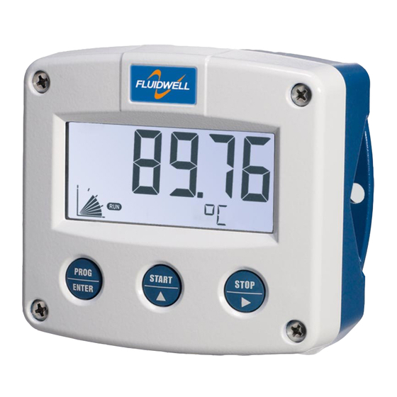
- Page 1 F040-T TEMPERATURE INDICATOR Signal input sensor: PT100 Options: Intrinsically Safe. F-Series - Field mounted indicators for safe and hazardous areas. More info: www.fluidwell.com/fseries...
-
Page 2: Safety Instructions
This unit must be installed in accordance with the EMC guidelines (Electro Magnetic Compatibility). Do connect a proper grounding to the aluminum casing as indicated if the F040-T has been supplied with the 115-230V AC power-supply type PM. The green / yellow wire between the back-casing and removable terminal-block may never be removed. -
Page 3: About The Operation Manual
This operation manual describes the standard unit as well as most of the options available. For additional information, please contact your supplier. A hazardous situation may occur if the F040-T is not used for the purpose it was designed for or is used incorrectly. Please carefully note the information in this operating manual indicated by the pictograms: A "warning"... -
Page 4: Table Of Contents
Safety rules and precautionary measures ....................... 2 About the operation manual ..........................3 Contents manual .............................. 4 Introduction ..........................5 1.1. System description of the F040-T ..................5 Operational ..........................6 2.1. General ..........................6 2.2. Control panel .......................... 6 2.3. -
Page 5: Introduction
Fig. 1: Typical application for the F040-T. Configuration of the unit The F040-T has been designed to be implemented in many types of applications. For that reason, a SETUP-level is available to configure your F040-T according to your specific requirements. -
Page 6: Operational
Take careful notice of the " Safety rules, instructions and precautionary measures " in the front of this manual. This chapter describes the daily use of the F040-T. This instruction is meant for users / operators. 2.2. CONTROL PANEL The following keys are available: Fig. -
Page 7: Operator Information And Functions
SETUP-settings. The signal generated by the connected sensor is measured by the F040-T in the background, whichever screen refresh rate setting is chosen. After pressing a key, the display will be updated very quickly during a 30 second period, after which it will slow-down again. -
Page 8: Configuration
Personnel must read and understand this Operating Manual before carrying out its instructions. The F040-T may only be operated by personnel who are authorized and trained by the operator of the facility. All instructions in this manual are to be observed. - Page 9 Page 9 Matrix structure SETUP-level: SCROLLING THROUGH SETUP-LEVEL Selection of function-group and function: SETUP is divided into several function groups and functions. Each function has a unique number, which is displayed below the word "SETUP" at the bottom of the display. The number is a combination of two figures. The first figure indicates the function-group and the second figure the sub-function.
- Page 10 Page 10 To change or select a value: To change a value, use to select the digits and to increase that value. If the new value is invalid, the increase sign or decrease-sign will be displayed while you are programming.
-
Page 11: Overview Functions Setup Level
- 1 sec - 3 sec - 15 sec - off BATTERY MODE operational - shelf SENSOR NR OF WIRES 2 - 3 - 4 FILTER 0 - 99 OTHERS TYPE / MODEL F040-T SOFTWARE VERSION 03.xx.xx SERIAL NO. xxxxxxx PASS CODE 0000 - 9999 TAGNUMBER 0000000 - 9999999 3.2.3. -
Page 12: Power Management
When used with the internal battery option, the user can expect reliable measurement over a long period of time. The F040-T has several smart power management functions to extend the battery life time significantly. Two of these functions can be set:... -
Page 13: Others
For support and maintenance it is important to have information about the TYPE OF MODEL characteristics of the F040-T. Your supplier will ask for this information in the case of a serious breakdown or to assess the suitability of your model for upgrade considerations. -
Page 14: Installation
Personnel must read and understand this Operating Manual before carrying out its instructions. The F040-T may only be operated by personnel who are authorized and trained by the operator of the facility. All instructions in this manual are to be observed. -
Page 15: Dimensions- Enclosure
Page 15 4.3. DIMENSIONS- ENCLOSURE Aluminum enclosures: 75 mm (2.95") 112 mm (4.40") 130 mm (5.12") 12mm 12mm 30mm 30mm 24mm 24mm M20 x 1,5 6 x M12 36mm 36mm 30mm 30mm M16 x 1,5 M16 x 1,5 1/2"NPT M20 x 1,5 0.12"... - Page 16 Page 16 GRP enclosures: 75 mm (2.95") 112 mm (4.40") 130 mm (5.12") HK back box: (flat bottom) 75 mm (2.95") 118 mm (4.65”) 25mm 25mm D=20mm D=20mm 12mm 12mm 30mm 30mm 24mm 24mm D=12mm D=16mm D=16mm D=20mm 36mm 36mm 0.12”...
-
Page 17: Installing The Hardware
This unit must be installed in accordance with the EMC guidelines (Electro Magnetic Compatibility). Do ground the aluminum casing properly as indicated, if the F040-T has been supplied with the 115-230V AC power-supply type PM. The green / yellow wire between the back-casing and removable terminal-block may never be removed. -
Page 18: Terminal Connectors With Power Supply - Type : Pb / Px
PT100 - 2 WIRE PT100 - 3 WIRE PT100 - 4 WIRE Fig. 8: Overview of terminal connectors F040-T-(PB / PX) and options. REMARKS: TERMINAL CONNECTORS: Terminals 1-4; Sensor input type T – PT100: See drawing above for the proper connection of a 2, 3 or 4 wire PT100 sensor. The sensor signal which will be processed once per second with a 16 bits accuracy. -
Page 19: Terminal Connectors With Power Supply - Type : Pf / Pm
PT100 - 2 WIRE PT100 - 3 WIRE PT100 - 4 WIRE Fig. 9: Overview of terminal connectors F040-T-(PF / PM) and options. REMARKS: TERMINAL CONNECTORS: Terminal GND- 01- 02; POWER SUPPLY only available with type PF / PM: erminal... -
Page 20: Intrinsically Safe Applications
For installation under FM: this intrinsically safe device must be installed in accordance with the Certificate / Project ID: 3033306. The control drawing number FWCD-0005 can be found in the document named: “Fluidwell F0..-T-XI - Documentation for Intrinsic Safety”. -
Page 21: Terminal Connectors Intrinsically Safe Applications
FWCD-0005. Tamb CSA Certificate nr: CSA.08.2059461 – FM Project ID: 3033306 -40°C ... +70°C Made in Veghel, The Netherlands by Fluidwell bv -40°F ... +158°F KEMA 05ATEX1168 X Battery powered applications: II 1 G Ex ia IIC T4 Replace with certified II 1 D Ex iaD 20 IP 65 / 67 T 100°C... -
Page 22: Configuration Examples Intrinsically Safe Applications
Type PX: as standard, all intrinsically safe products are supplied with terminal 4 and 5 to power the product externally. 5.3. CONFIGURATION EXAMPLES INTRINSICALLY SAFE APPLICATIONS: Configuration example Configuration example IIA - IIB and IIC application - F040-T-PX-XI-ZB HAZARDOUS AREA SAFE AREA TERMINAL CONNECTORS F0-series = max. -
Page 23: Battery Replacement Instructions
Page 23 5.4. BATTERY REPLACEMENT INSTRUCTIONS FW-LiBAT-001 - INST001 Fig. 14: Battery replacement instructions Intrinsically Safe Battery. HF040TEN_v0402_03 Atex_IECEx_CSA_FM... -
Page 24: Maintenance
Personnel must read and understand this Operating Manual before carrying out its instructions. The F040-T may only be operated by personnel who are authorized and trained by the operator of the facility. All instructions in this manual are to be observed. -
Page 25: Appendix A: Technical Specification
Page 25 APPENDIX A: TECHNICAL SPECIFICATION GENERAL Display Type High intensity reflective numeric and alphanumeric LCD, UV-resistant. Digits 5 ½ 26mm (1") and eleven 8mm (0.31"). Various symbols and measuring units. Piegraph 10 segment range indication in relation to its measuring range 0-100% Refresh rate User definable: 8 times/sec - 30 secs. - Page 26 Page 26 Data protection Type EEPROM backup of all settings. Data retention at least 10 years. Pass code Configuration settings can be pass code protected. Hazardous area (option) Intrinsically safe ATEX approval: Type XI II 1 G Ex ia IIC T4 II 1 D Ex iaD 20 IP 65 / 67 T 100°C IECEx approval: Ga Ex ia IIC T4...
-
Page 27: Appendix B: Problem Solving
Page 27 APPENDIX B: PROBLEM SOLVING In this appendix, several problems are included that can occur when the F040-T is going to be installed or while it is in operation. Range error Range error: the input value is at least 5% above or below the calibrated measurement range. -
Page 28: Index Of This Manual
Page 28 INDEX OF THIS MANUAL actual settings maintenance alarm 7, 27 manual version backlight model color operational density operator level battery life time 11, 12, 24 pass code 13, 27 Battery replacement power supply 18, 19 configuration problem solving contents range error 7, 27... -
Page 29: List Of Figures In This Manual
Fig. 7: Dimensions GRP enclosures....................16 Fig. 7: Grounding aluminum enclosure with option PM 115-230V AC..........17 Fig. 8: Overview of terminal connectors F040-T-(PB / PX) and options..........18 Fig. 9: Overview of terminal connectors F040-T-(PF / PM) and options..........19 Fig. -
Page 30: Notes
Page 30 NOTES HF040TEN_v0402_03 Atex_IECEx_CSA_FM... - Page 31 Page 31 NOTES HF040TEN_v0402_03 Atex_IECEx_CSA_FM...
- Page 32 54 pass code 0000 55 tagnumber 0000000 Fluidwell bv HF040TEN_v0402_03 Atex_IECEx_CSA_FM PO box 6 Voltaweg 23 Website: www.fluidwell.com 5460 AA Veghel 5466 AZ Veghel Find your nearest representative: www.fluidwell.com/representatives The Netherlands The Netherlands Copyright Fluidwell bv - 2012 - HF110AEN_v0501_03...
Need help?
Do you have a question about the F040-T and is the answer not in the manual?
Questions and answers