Datavideo SE-500 Instruction Manual
Digital video switcher
Hide thumbs
Also See for SE-500:
- Instruction manual (55 pages) ,
- Specifications (2 pages) ,
- Instruction manual (52 pages)

Related Manuals for Datavideo SE-500


Summary of Contents for Datavideo SE-500
- Page 1 Digital Video Switcher SE-500 Error! INSTRUCTION MANUAL Http://www.datavideo-tek.com Rev 300606...
-
Page 2: Table Of Contents
Table of Contents Warnings and Precautions Warnings and Precautions Radio and Television Interference Warranty Disposal Introduction Introduction Product overview Features Packing List Installation, Connections, Set Up Some General Notes on Installation Power Up State Connecting Video sources Connecting Audio sources Outputs and Monitoring Audio Mixer RS-232 control... - Page 3 How does RS 232 work in practice Appendix Glossary of terms Tech notes (Video Standards, Formats, and Quality; Monitor Calibration) Specifications Useful Accessories RS-232 Remote Control Commands MIDI Control Commands Tally Pinouts cross reference between the TLM-404 & the SE-500 Service and Support...
-
Page 4: Warnings And Precautions
7. This product should only be operated from the type of power source indicated on the marking label of the AC adapter. If you are not sure of the type of power available, consult your Datavideo dealer or your local power company. -
Page 5: Warranty
Equipment that fails after the warranty period, has been operated or installed in a manner other than that specified by Datavideo, or has been subjected to abuse or modification, will be repaired for time and material charges at the Buyer’s expense. This warranty does not affect your statutory rights within the Country of purchase. -
Page 6: Product Overview
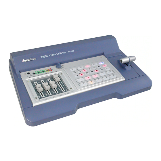
Product Overview The Datavideo SE-500 is an analog input, digital processing video switcher. The SE-500 includes 4 groups of video input (4 x composite & 4 x S-Video), a 3 channel audio mixer, 2 microphone inputs, color correction, digital video transition effects, MIDI control interface, Tally out, RS-232 remote control interface…and many more professional features. -
Page 7: Installation, Connections, Setup
Finally, for examples of how to connect and integrate the SE-500 into a variety of set ups, take a look at the brief Quick Start on page 9 and the more in depth explanations in Sample Applications on page 29. -
Page 8: Connecting Video Sources
Connecting Audio Sources The SE-500 uses 2 kinds of plugs for audio connections: RCA and 1/4 inch jack plugs. There are lots of different names for these plugs. Fortunately for us all, they are not easily confused in the size and shape departments, so we’ll show you some pictures. -
Page 9: Audio Mixer
52. MIDI control Connects to other MIDI devices, such as MIDI keyboard, and electronic piano. Refer to the Appendix detail of MIDI Control Protocol, page 50. Connecting a Datavideo TLM-70D 7” TFT LCD for preview video monitoring, page 43. -
Page 10: Quick Start
Quick Start SE-500 Front Panel 1. Audio faders 2. Headphone Socket 3. Audio meters 4. Headphone Volume Control 5. Video Effect: Quad 6. Video Effect: Split 7. Video Effect: PIP 8. Video Effect: Freeze 9. Background color selection/Menu 10. Border On/Off 11. - Page 11 1. Faders: sliders to control audio levels for the Main audio output mix. These Audio Level pots are the first stage in the audio signal path. Analog audio comes in through the 1/4 inch phono jack and RCA connectors on the rear panel see Rear Panel, page 13.
- Page 12 9. Background: When Background is selected in either the Main or Sub Video Source (13, 14.), and the button is pressed (and the LED is lit except with black color background), repeated presses of the color button cycle through the 8 possible solid backgrounds. For more information, see Background, page 28.
- Page 13 Using Transitions, page 23 and Using Effects, page 26. Tech note for example, from composite video to S-video. The SE-500 has been designed to perform transcoding, as part of its standard operating procedure. Select a video source on the Main Source Input bus, and it will be available at the Main Output in all formats, S-Video and Composite, simultaneously.
-
Page 14: Se-500 Rear Panel
SE-500 Rear Panel 1. Video inputs, Channels 1, 2, 3, 4. 1a. S-Video (Y/C) input 1b. Composite video input (BNC) 2. Video outputs 2a. Composite video out (BNC) 2b. S-video (Y/C) out 2c. Component (Combine Composite & Y/C with supplied breakout cable)* 2d. - Page 15 N.B If S-Video (Y/C) is connected it will be automatically selected in priority over Composite. 2. Video Output. These ports carry the Main video output of the SE-500. a. Composite video out: BNC connector typically connected to a program monitor.
- Page 16 (see Controls and Operations, page 19). 10. Power: Switches the unit On / Off. 11. DC Input: connect the power supply that came with the SE-500, and only the power supply that came with the SE-500, here, and plug the other end into an electrical...
-
Page 17: Selecting Video Input Formats And Adjusting Audio Levels
Selecting video output format In addition to the Composite Video Output the SE-500 can output either S-Video (Y/C) or Component Video (YUV). To output Component Video there is a special breakout cable that connects to the (Y/C) out and one of the Composite Outputs. -
Page 18: Dissolving Between Sources
Effects There are two places on the SE-500 where you can add effects: in the Transition Effects section (15.) and in the Video Effects section (5-8.). Some of these work on a single source, and some need two or four sources to work. - Page 19 PIP effect (7.), which stands for Picture in Picture. As you might guess, this effect requires a Main and Sub Video Source. Assuming you have valid inputs on Channel 1 and 2, select Channel 1 as the Main Source and Channel 2 as the Sub Source. When you engage the effect by pressing the PIP button (and verifying that the LED on the button is lit), on the program monitor you will have Channel 1 as the Main Source and Channel 2 as a smaller window inset.
-
Page 20: Controls And Operations
The frozen image is a function of how the time base corrector (TBC, a.k.a. frame synchronizer) works. The SE-500 has a TBC at the Main Video Source and the Sub Video Source input on each channel. Their purpose is to stabilize the video signals as they come into the switcher, and to synchronize their timing... -
Page 21: Color Processor
“MENU” section. These controls are like picture controls on a video monitor or the proc amp (processing amplifier) controls on a time base corrector. In fact, they are the proc amp controls of one of the SE-500’s 4 internal TBCs. -
Page 22: Menu
Component output signal. If you use a MIDI keyboard in live concerts, you can control the SE-500. Go to “Remote Control”, use + or - to change the setting from RS-232C to MIDI. Press “BACKGROUND” again, select the desired MIDI channel you wish to use. -
Page 23: Audio Inputs, Levels, And Meters
Audio Input Level Calibration Procedure The first step in setting up the audio for a session with your SE-500 consists of adjusting the levels on which channel you will be using. Slide the Master fader to Max, and set the other faders to 0. Then, listening to the... -
Page 24: Using Transitions
Using Transitions The SE-500 can do 3 kinds of transitions: cut, fade, and wipe. The cut is a simple switch from one input source to another, and can be accomplished by selecting a source on the Main Source Bus, and then selecting a second one. -
Page 25: List Of Transitions
List of transitions and parameters Wipe (works in conjunction with Border controls): Block wipe from center to full screen. Right angle wipe on, upper right to lower left Right angle reveal, lower right to upper left Right angle wipe on, upper left to lower right Right angle reveal, lower left to upper right Horizontal wipe, top to bottom Horizontal wipe, bottom to top... - Page 26 Vertical wipe, middle to left and right Horizontal wipe, middle to top and bottom...
-
Page 27: Using Effects
Using Effects The SE-500 is capable of producing a wide variety of digital effects. These falls into 2 categories: single channel and dual channel effects. Single channel effects are produced on the source selected in the Main Video Source bus and need no second video input. -
Page 28: Effects: Quad
Effects: Quad The Quad effect combines 4 input videos into 1 output. When this effect is activated, it shows 4 video sources on 1 single monitor. Each source takes one quarter of the entire screen. Press the button again, and it returns to the previous selected source in full screen. -
Page 29: Border
Border These controls are used in conjunction with the Picture in Picture Effect and Wipe transition only, and can only be activated when the Picture in Picture or Wipe control is active. 8 Colors are available for the wipe border: black, blue, magenta, red, green, cyan, yellow and white. See “Background Color”... -
Page 30: Sample Applications
Sample applications We figured, being practical minded, that the best way to show off what the SE-500 can do is to give you some examples of how it could be used in real life situations. Each example refers to a block diagram for set up and connections. -
Page 31: Four Camera Shoot: Live Stage Performance/Sporting Event
The four cameras are feeding analogue signals to the SE 500, via Composite or S-Video. It would be possible to use DV cameras by adding a Datavideo DAC 6 to each of the channels that you want to run DV. -
Page 32: Live Conference
Live Conference In this second example we see a typical conference set up. There are two cameras to handle the speaker and the overview, with audience reaction or other action on the stage. Both cameras are analogue, but by adding a DAC 6 to any of the channels it would be possible to use a DV camera. -
Page 33: Live Event Mixing: Club Vj/Concert
Live Event Mixing: Club VJ / Concert In our final example we are looking at a typical V.J. set up. Increasingly in clubs video images are used to add to the overall effect and atmosphere, they are combined with light displays and other audio / visual effects. -
Page 34: Using Se-500 With Cg-100 For Titles/Graphics/Logos Overlay
To Master Recorder Deck To Projector Using YUV output (with a breakout cable) on SE-500 to communicate with a PC with Decklink SP CG overlay card and CG-100 CG software (page 42) to perform a text overlay for the output video. -
Page 35: Troubleshooting / Faq
Check that the power supply is plugged into the SE 500, and to a suitable mains outlet, and that it is switched on. Move the SE-500 to a cooler location and allow the unit time to cool off before powering on again. No image at output / black and white output from S (Y/C) Make sure that there is an image from all your Video Input sources on the quad preview monitor. -
Page 36: Appendix
Appendix Glossary of Terms Analog video: a video signal that is recorded and played back using changes in magnetic levels recorded a tape or disk, e.g., the video we see when we watch a VHS videocassette. Animation: a video or film sequence that gives the illusion of motion by presenting a series of images or photographs. - Page 37 S-video: Y/C separated video, used with a specific round, 4 pin plug. Sync: electronic pulses that synchronize the scan rates of different components (cameras, recorders, switcher, etc.) in a video system. THD (Total Harmonic Distortion): Of a signal (most often audio), the ratio of the sum of the powers of all harmonic frequencies above the fundamental to the power of the fundamental, usually expressed in dB.
-
Page 38: Tech Notes (Video Standards, Formats, And Quality; Monitor Calibration)
Vector scope: a test instrument for displaying color hue and saturation in a video signal used to aid in color correction. Waveform monitor: a test instrument which shows a graphical representation of the luminance levels of the video waveform, used, in conjunction with a vectorscope, as an aid in color and image correction and video system set up. -
Page 39: Monitor Calibration (Procedures, Test Patterns/Bars)
of the signal to reveal how bad it actually is or where the problems actually lie. The context in this case is the display, the quality of the monitor. As video makers, we have to produce to the quality specifications our clients’ demand, what is appropriate for the project, what they can afford. - Page 40 But, if you don’t have a waveform monitor/vector scope to adjust incoming video, you can make those adjustments by eye, using the SE-500’s color processing controls, now that you have a properly calibrated program monitor. The process for each input channel will be very similar to the process we just used to calibrate the program monitor, except we were adjusting the controls on the monitor, and now we will be adjusting the controls on the SE-500.
-
Page 41: Specifications
Specifications Video Formats Analog Y/C, Composite CCIR601 NTSC and PAL (PAL and NTSC are separate models) Video Inputs 4 – S (Y/C), Composite Video Output 1 – Quad Video source monitoring (Composite) 2 – Composite 1 – S (Y/C) 1 – Component (With breakout cable, it uses the S (Y/C), and one Composite output.) Audio Inputs 1 –... - Page 42 Audio 20 to 20KHz +/-1dB Audio THD <0.1% Dimensions W x D x H 15.75" x 10.5" x 3.25" (Approx) 400mm x 265mm x 83mm (Approx) Weight 13.8 lb, 5.5 Kg Power Input: DC 12V, 1.5A...
-
Page 43: Useful Accessories
Datavideo CG- CG-100 THE FIRST AFFORDABLE SDI CG SOLUTION LIVE SDI TITLE / GRAPHIC / LOGO OVERLAY CG-100 can be used in any SDI or YUV input switchers. It can be also used in SE-500 via YUV output interfaces. SDI overlay offers the best, broadcast quality, CG solution in the industry today. -
Page 44: Datavideo Dac-6 Dv To Analog (One Way Converter)
TV wall. With a vision mixer / switcher such as the SE-800, you can also combine DVD player, DV camera, VCR, VHS and CD player for a perfect presentation. -
Page 45: Datavideo Bac-03 Balanced-Unbalanced Audio Converter
20 meters for cable runs of up to 200 meters One input to five channels output DV-DA (VP-332) Please check website (www.datavideo-tek.com) for the most up to date list, descriptions, and pricing of accessories for the SE-800. UNBAL to BAL output... -
Page 46: Rs-232 Remote Control Commands
SE500 RS-232 Remote Control Command 1. Physical layer Control output format: RS-232C Communication rate: 57600 BPS Data format: 8 bits serial, LSB first, 1 start bit, 1 stop bit, odd parity Must delay 100uSEC between 2 bytes 2. Data link layer 2.1 Frame format Header Length Data0 Data1 Data2 Data3... - Page 47 1) The command group 05h (base 16) = SE500 control command 2) The operated refer to section 4. 3.2 Return data format Command parameter Status 1) The command status 05h=SE500 control command status 2) The parameter refers to section 6. The operated of SE500 control command Operated Operated...
- Page 48 15h= key_left_bottom_block 16h= key_top_block 17h= key_bottom_block 18h= key_right_block 19h= key_left_block 1ah= key_horizontal 1bh= key_vertical 20h= key_border_on 22h= key_background_color 24h= key_speed* 26h = key_PIP 3bh = key_menu 3ch = key_up 3dh = key_down 3eh = key_left 3fh = key_right 40h = key_reset 41h = key_plus 42h = key_minus *Note: Send the key_speed code to the SE500,the speed of effect will be changed follow below rule.
- Page 49 4) The effect No. The value from 0 to 99(63h) Fade effect No. = 0 Wipe effect No.= 0 to 10 Quad effect No.= 0 POP effect No. = 0 to 1 PIP effect No.:bit3 to bit0= x0h to x4h (position) Bit4=0=big size, bit4=1=small size Bit5=0=not shift, bit5=1=shift to close center.
- Page 50 7. EXAMPLE 1) PC control SE500, key command = key_take= 0fh a.) The command stream = F0h,32h,0eh,05h,01h,0fh,,30h,34h,ffh Header=F0h ID=32h Length = 9 bytes=09h Command group=05h Command mode=normal control code=01h Control key code=key_take =0fh checksum= (f0h+32h+09h+05h+01h+0fh) = 40h checksum_low =00h+30h = 30h checksum_high=04h+30h = 34h END =ffh b.) SE500 return data,...
-
Page 51: Se500 Midi Remote Control Command
SE500 MIDI Remote Control Command 1. Physical layer Follow the MIDI SPEC. 1.0 Communication rate: 31250 BPS Data format: 8 bits serial, LSB first, 1 start bit, 1 stop bit, none parity 2. Data link layer 2.1 Control messages = MIDI Channel voice messages * Received only if Note Mode is ON * The input of each channel is selected. - Page 52 4. Example 1. Change the transition effect to fade = 90H, 30H, 64H 90H= Note on, Channel =1 (IF the SE500’s MIDI channel is 1) 30H=Note No 48=fade key 64H= Velocity value > 0 2. Take the transition effect = 90H, 47H, 64H 47H=Note No 71=Take key * Very Easy to use, any MIDI keyboard can control the SE500.
-
Page 53: Se500 Tally Pin Outs Cross Reference
SE500 Tally Pin Outs Cross Reference Release date: 2005/07/07 LED A3 = pin 1 LED A2 = pin 2 LED A1 = pin 3 Ground = pin 4 LED D3 = pin 5 LED B3 = pin 6 LED B2 = pin 7 LED B1 = pin 8... -
Page 54: Product Registration
Your name: Your mailing Address: Email address: May we include you in our mailing list to learn about new Datavideo products? Yes/No Why did you buy the SE-500? Do you have a COMPONENT video recorder or player? What video sources will you use with the SE-500? -
Page 55: Service And Support
It is our goal to make your products ownership a satisfying experience. Our supporting staff is available to assist you in setting up and operating your system. Please refer to our web site www.datavideo-tek.com for answers to common questions, support requests or contact your local office below.
Need help?
Do you have a question about the SE-500 and is the answer not in the manual?
Questions and answers