Table of Contents
Advertisement
Quick Links
Advertisement
Table of Contents

Subscribe to Our Youtube Channel
Related Manuals for IFM O5P7 Series


Summary of Contents for IFM O5P7 Series
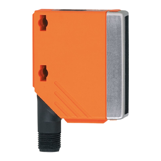
- Page 1 Operating instructions Retro-reflective sensor O5P7xx...
- Page 2 1 Preliminary note 1.1 Symbols used ► Instruction > Reaction, result […] Designation of pushbuttons, buttons or indications → Cross-reference Important note Non-compliance can result in malfunctions or interference. 2 Safety instructions According to the cULus approval Caution - Use of controls or adjustments or procedures other than those specified herein may result in hazardous radiation exposure.
- Page 3 4 Installation ► Fit the prismatic reflector or the reflective tape behind the object to be detected. ► Align the retro-reflective sensor to it and secure it to a bracket. Maximum range is only possible with precise alignment. 5 Operating and display elements 1: LED 2: [OUT on] 3: [OUT off]...
- Page 4 ► Disconnect power. ► Connect the unit as follows: DC PNP pin 1 = L+ (10...36 V DC) (pin 2 = not connected) pin 3 = L- pin 4 = load (PNP, 200 mA) 7 Settings 7.1 The sensor is to switch when the object is detected ►...
- Page 5 ► For cleaning do not use any solvents or cleaning agents which could damage the plastic material. ► Do not try to open the module enclosure. There are no user - serviceable components inside. Technical data and further information at www.ifm.com...
Need help?
Do you have a question about the O5P7 Series and is the answer not in the manual?
Questions and answers