Motorola APX 7000 User Manual
Dual display
Hide thumbs
Also See for APX 7000:
- Detailed service manual (644 pages) ,
- Basic service manual (292 pages) ,
- User manual (213 pages)

Related Manuals for Motorola APX 7000


Summary of Contents for Motorola APX 7000
- Page 1 APX TWO-WAY RADIOS DUAL DISPLAY APX 7000/APX 7000L USER GUIDE DECEMBER 2019 *6875945M01* 6875945M01-NL © 2019 Motorola Solutions, Inc. All rights reserved...
-
Page 2: Table Of Contents
6875945M01-NL Contents Contents Declaration of Conformity..................11 Important Safety Information................... 13 Notice to Users (FCC and Industry Canada)............14 Software Version.......................15 Computer Software Copyrights................16 Documentation Copyrights..................17 Disclaimer........................18 Read Me First......................19 Notations Used in This Manual....................19 Radio Maintenance........................19 Radio Care........................19 Cleaning Your Radio.................... - Page 3 6875945M01-NL Contents Radio Controls......................31 Radio Parts and Controls......................31 Programmable Features......................32 Assignable Radio Functions..................... 32 Assignable Settings or Utility Functions................35 Accessing the Preprogrammed Functions...................35 Menu Select Buttons......................36 Home Button........................36 4-Way Navigation Button....................36 Data Feature Button......................36 Keypad............................37 Keypad Characters – Uppercase Mode................37 Keypad Characters –...
- Page 4 6875945M01-NL Contents 1.6 Methods to Make a Radio Call....................57 1.6.1 Making a Talkgroup Call ..................58 1.6.2 Making a Private Call (Trunking Only)..............58 1.6.3 Making an Enhanced Private Call (Trunking Only)..........59 1.6.4 Making a Telephone Call (Trunking Only)............... 59 1.7 Switching Between Repeater or Direct Operation Button............60 1.8 Monitor Feature........................
- Page 5 6875945M01-NL Contents 2.3.6.3 Editing a Call Type..................75 2.3.7 Viewing Details of a Contact..................75 2.4 Scan Lists..........................75 2.4.1 Intelligent Priority Scan.................... 76 2.4.2 Viewing a Scan List....................76 2.4.3 Editing the Scan List....................76 2.4.4 Changing the Scan List Status.................77 2.4.5 Viewing and Changing the Priority Status..............77 2.5 Scan............................78 2.5.1 Turning Scan On or Off....................78...
- Page 6 6875945M01-NL Contents 2.11.3 Radio Alerts When Man Down Feature is Triggered..........90 2.11.4 Triggering Emergency....................90 2.11.5 Radio Alerts When Man Down Enhanced is Triggered..........91 2.11.6 Exiting Man Down Feature..................91 2.11.7 Re-Initiating Man Down..................91 2.11.8 Testing the Man Down Feature................92 2.12 Automatic Registration Service (ARS).................92 2.12.1 Selecting or Changing the ARS Mode..............
- Page 7 6875945M01-NL Contents 2.15.3 Managing Encryption................... 107 2.15.3.1 Loading Encryption Keys............... 107 2.15.3.2 Multikey Feature..................108 2.15.3.3 Selecting Encryption Keys..............108 2.15.3.4 Selecting Keysets...................109 2.15.3.5 Erasing Encryption Keys................ 109 2.15.3.6 Requesting an Over-the-Air Rekey............110 2.15.3.7 MDC Over-the-Air Rekeying Page (Conventional Only)......110 2.15.3.8 Infinite UKEK Retention.................
- Page 8 2.22.2 Turning Off the Bluetooth..................127 2.22.3 Re-Pair Timer.......................128 2.22.4 Bluetooth Drop Timer...................128 2.22.5 Pairing with Low Frequency-Motorola Proximity Pairing (LF-MPP) Feature..129 2.22.6 Radio Indications of Lost Bluetooth Connection..........130 2.22.7 Standard Pairing Feature..................130 2.22.7.1 Searching and Pairing the Bluetooth Device..........131 2.22.7.2 Turning On Bluetooth Visibility...............
- Page 9 6875945M01-NL Contents 2.23.1 Responding to the Notification of Upgrade............140 2.24 Voice Announcement ......................141 2.25 Site Selectable Alerts (ASTRO 25)..................141 2.25.1 Sending SSA Notification to Single Site...............141 2.25.2 Sending SSA Notification to Single Site by Manual Entry........142 2.25.3 Sending SSA Notification to All Sites..............143 2.25.4 Sending SSA Notification to All Available Sites...........
- Page 10 4.3 Declaration of Compliance for the Use of Distress and Safety Frequencies....... 170 4.4 Technical Parameters for Interfacing External Data Sources..........170 Glossary........................171 Limited Warranty.....................178 6.1 MOTOROLA SOLUTIONS COMMUNICATION PRODUCTS..........178 6.2 I. WHAT THIS WARRANTY COVERS AND FOR HOW LONG:......... 178 6.3 II. GENERAL PROVISIONS:....................179 6.4 III. STATE LAW RIGHTS:....................179 6.5 IV.
-
Page 11: Declaration Of Conformity
Name: Motorola Solutions, Inc. Address: 1303 East Algonquin Road, Schaumburg, IL 60196-1078, U.S.A. Phone Number: 1-800-927-2744 Hereby declares that APX 7000/APX 7000L conforms to FCC Part 15, subpart B, section 15.107(a), 15.107(d), and section 15.109(a) Class B Digital Device As a personal computer peripheral, this device complies with Part 15 of the FCC Rules. This device complies with Industry Canada license-exempt RSS standard(s). - Page 12 If you have already purchased the radio with the Bluetooth Option Board as part of the tanapa and you need to replace (repair) the option board, you can send the radio to any Motorola Solutions FM audited.
-
Page 13: Important Safety Information
Before using the radio, read the RF Energy Exposure and Product Safety Guide for Portable Two-Way Radios which contains important operating instructions for safe usage and RF energy awareness and control for Compliance with applicable standards and Regulations. For a list of Motorola Solutions-approved antennas, batteries, and other accessories, visit the following website: http://www.motorolasolutions.com Under Industry Canada regulations, this radio transmitter may only operate using an antenna of a type and maximum (or lesser) gain approved for the transmitter by Industry Canada. -
Page 14: Notice To Users (Fcc And Industry Canada)
• This device must accept any interference received, including interference that may cause undesired operation. • Changes or modifications made to this device, not expressly approved by Motorola Solutions, could void the authority of the user to operate this equipment. -
Page 15: Software Version
6875945M01-NL Software Version Software Version All the features described in the following sections are supported by the software version R20.60.00 or later. Accessing the Radio Information on page 161 to determine the software version of your radio. Check with your dealer or system administrator for more details of all the supported features. -
Page 16: Computer Software Copyrights
The Motorola Solutions products described in this manual may include copyrighted Motorola Solutions computer programs stored in semiconductor memories or other media. Laws in the United States and other countries preserve for Motorola Solutions certain exclusive rights for copyrighted computer programs including, but not limited to, the exclusive right to copy or reproduce in any form the copyrighted computer program. -
Page 17: Documentation Copyrights
No duplication or distribution of this document or any portion thereof shall take place without the express written permission of Motorola Solutions. No part of this manual may be reproduced, distributed, or transmitted in any form or by any means, electronic or mechanical, for any purpose without the express written permission of Motorola Solutions. -
Page 18: Disclaimer
The information in this document is carefully examined, and is believed to be entirely reliable. However, no responsibility is assumed for inaccuracies. Furthermore, Motorola Solutions reserves the right to make changes to any products herein to improve readability, function, or design. Motorola Solutions does not assume any liability arising out of the applications or use of any product or circuit described herein;... -
Page 19: Read Me First
6875945M01-NL Read Me First Read Me First This User Guide covers the basic operation of the radio. However, your dealer or system administrator may have customized your radio for your specific needs. Check with your dealer or system administrator for more information. If you attempt to use features which are mutually exclusive, one or more of the following occurs: •... - Page 20 • (For APX 7000/APX 7000L R Radios Only) Your radio is designed to be submerged to a maximum depth of 6 feet, with a maximum submersion time of 2 hours. Exceeding either maximum limit may result in damage to the radio.
-
Page 21: Cleaning Your Radio
Radio Service and Repair Proper repair and maintenance procedures ensures efficient operation and long life for this product. A Motorola Solutions maintenance agreement will provide expert service to keep this and all other communication equipment in perfect operating condition. A nationwide service organization is provided by Motorola Solutions to support maintenance services. - Page 22 6875945M01-NL Read Me First • The fuel gauge icon on the display You can also check the battery charge status using the menu entry. See IMPRES Battery Annunciator on page 161 for more information. LED and Sounds When your battery is low: •...
-
Page 23: Battery Recycling And Disposal
Read Me First Battery Recycling and Disposal In the U.S. and Canada, Motorola Solutions participates in the nationwide Call2Recycle program for battery collection and recycling. Many retailers and dealers participate in this program. For the location of the drop-off facility closest to you, go to http://www.call2recycle.org/... -
Page 24: P25 Digital Vehicular Repeater System (Dvrs)
P25 Digital Vehicular Repeater System (DVRS) Motorola Solutions offers an MSI Certified APX compatible, third Party, P25 Digital Vehicular Repeater System (DVRS) that provides low-cost portable radio coverage in areas where only mobile radio coverage is available and portable radio coverage is either intermittent or non-existent. -
Page 25: Preparing Your Radio For Use
NOTICE: When charging a battery attached to a radio, turn the radio off to ensure a full charge. Procedure: To charge the battery, place the battery (with or without the radio) in a Motorola Solutions- approved charger. The LED on the charger indicates the charging progress; see the Charger User Guide. -
Page 26: Attaching The Antenna
6875945M01-NL Preparing Your Radio for Use 2 To remove the battery, turn the radio off. Squeeze the release latches at the bottom of the battery until the battery releases from the radio and remove the battery from the radio. Attaching the Antenna Prerequisites: Ensure the radio is turned off before attaching the antenna. -
Page 27: Removing And Attaching The Accessory Connector Cover
6875945M01-NL Preparing Your Radio for Use 3 To remove the antenna, turn the antenna counterclockwise. NOTICE: When removing the antenna, ensure that the radio is turned off. Removing and Attaching the Accessory Connector Cover When and where to use: The accessory connector is on the antenna side of the radio. It is used to connect accessories to the radio. -
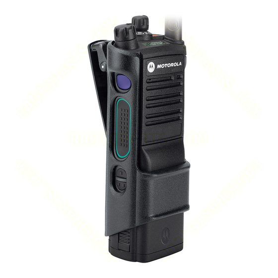
Page 28: Using The Carry Holder
6875945M01-NL Preparing Your Radio for Use Using the Carry Holder Procedure: 1 Position the radio within the carry holder with the main speaker facing outward. 2 Slide the radio down into the carry holder until it clicks in place. 3 To remove the radio from the carry holder, place the tip of your fingers on the ledge of the carry holder. -
Page 29: Turning On The Radio
6875945M01-NL Preparing Your Radio for Use Turning On the Radio Procedure: 1 Rotate the On/Off/Volume Control Knob clockwise until you hear a click. • If the power-up test is successful, the display shows SELFTEST momentarily, followed by the Home screen and the Codeplug Alias. •... -
Page 30: Adjusting The Volume
6875945M01-NL Preparing Your Radio for Use Adjusting the Volume Prerequisites: Ensure the radio is powered on and the main speaker is pointed towards you for increased loudness and intelligibility, especially in areas with loud background noises. Procedure: 1 To increase the volume, rotate the On/Off/Volume Control Knob clockwise. -
Page 31: Radio Controls
6875945M01-NL Radio Controls Radio Controls This chapter explains the buttons and functions to control the radio. Radio Parts and Controls Antenna Top (Orange) Button These radio controls/buttons are programmable. -
Page 32: Programmable Features
6875945M01-NL Radio Controls Microphone Accessory Connector Home Button 4–Way Navigation Button Keypad Data Feature Button Menu Select Buttons Main Display Secondary Speaker 2–Position Concentric Switch 3–Position A/B/C Switch On/Off/Volume Control Knob Top Side (Select) Button Push-to-Talk (PTT) Button Side Button 1 Side Button 2 Battery Latch Battery... - Page 33 6875945M01-NL Radio Controls Bluetooth Data Devices Pairs with the data devices for data transfer. Bluetooth Clear All Pairing Allows you to clear all pairing information for Bluetooth by pressing and holding the Bluetooth On/Off Button. Bluetooth Inquiry On/Off Enables the Bluetooth Search feature. Bluetooth Discoverable On/Off Enables Bluetooth visibility pressing and holding the Bluetooth Inquiry On/Off Button.
- Page 34 6875945M01-NL Radio Controls Monitor (Conventional Only) Monitors a selected channel for all radio traffic until the function is disabled. Multiple Private Line (Conventional Only) Selects the Multiple Private Line lists. Nuisance Delete Temporarily removes an unwanted channel, except for priority channels or the designated transmit channel from the scan list.
-
Page 35: Assignable Settings Or Utility Functions
6875945M01-NL Radio Controls Status (ASTRO 25 Trunking Only) Sends data calls to the dispatcher about a predefined status. Talkaround/Direct (Conventional Only) Toggles between using a repeater or communicating directly with another radio. Talkgroup (Conventional Only) Allows a call from an individual radio to a group of radios. Text Messaging Service (TMS) Selects the text messaging menu. -
Page 36: Menu Select Buttons
6875945M01-NL Radio Controls Softkeys Menu Select Buttons Data Feature Button 4–Way Navigation Button Home Button Menu Select Buttons NOTICE: Check with your dealer or system administrator for the list of features activated in your radio. Use the Menu Select button to access the menu entry of your radio feature. Your radio may be preprogrammed differently from the following example, but the steps for selecting a channel may appear as shown below: Press the Menu Select button directly below Chan . -
Page 37: Keypad
6875945M01-NL Radio Controls Keypad You can use the 3 x 4 alphanumeric keypad to access your radio features. The keypad functions in a manner similar to a standard telephone keypad when entering numeric digits. When the keypad is used to edit a list, each key can generate different characters of the alphabet. The following tables show the number of times a key needs to be pressed to generate the required character. -
Page 38: Keypad Characters - Lowercase Mode
6875945M01-NL Radio Controls Keypad Characters – Lowercase Mode Number of Times Key is Pressed & “ ‘ Toggle between mixed case mode, uppercase mode and lowercase mode. Space Toggle between numeric and letter mode. Keypad Characters – Numeric Mode Number of Times Key is Pressed &... -
Page 39: Keypad Characters - Hexadecimal Mode
6875945M01-NL Radio Controls Number of Times Key is Pressed Space Toggle between numeric and letter mode. Keypad Characters – Hexadecimal Mode Number of Times Key is Pressed... -
Page 40: Push-To-Talk (Ptt) Button
6875945M01-NL Radio Controls Number of Times Key is Pressed Not applicable Not applicable Push-To-Talk (PTT) Button The PTT button on the side of the radio serves two basic purposes: • While a call is in progress, the PTT button allows the radio to transmit to other radios in the call. Press and hold down PTT button to talk. -
Page 41: Status Indicators
6875945M01-NL Status Indicators Status Indicators This section explains the status indicators of the radio. Status Icons The 240 x 320 pixel front liquid crystal display (LCD) of your radio shows radio status, text entries, and menu entries. The top two display rows contain color icons that indicate radio operating conditions. Selected icons are also shown on the first row of the 112 x 32 pixel top monochrome display screen of your radio. - Page 42 6875945M01-NL Status Indicators Monitor (Carrier Squelch) Selected channel is being monitored (during conventional operation only). Top Display: In-Call User Alert The feature is enabled. Voice muting of the affiliated trunking talkgroup or selected conventional channel is activated. The feature is disabled. Voice muting of the affiliated trunking talkgroup or selected conventional channel is deactivated.
- Page 43 6875945M01-NL Status Indicators Radio is in Zone 4. Radio is in Zone 5. Radio is in Zone 6. Top Display: Enhanced Zone Bank Contains Zone 1, Zone 2, and Zone 3, Contains Zone 4, Zone 5, and Zone 6, until Contains Zone 7, Zone 8, and Zone 9, until Contains Zone 70, Zone 71, and Zone 72,...
- Page 44 6875945M01-NL Status Indicators Blinking Device registration or user registration with the server failed due to an in- valid username or pin. Inverted User successfully login to the secured IP Packet Data. Data Activity Data activity is present. Hexadecimal Indicates that the text entry is currently in hexadecimal mode. Numeric Indicates that the text entry is currently in numeric mode.
-
Page 45: Text Messaging Service (Tms) Indicators
6875945M01-NL Status Indicators LTE Transmitting The radio is transmitting LTE signal. LTE Receiving and Transmitting The radio is receiving and transmitting LTE signal. LTE with ARS User logged in Indicating ARS user logged in successfully with LTE system. LTE Receiving while ARS user logged in Indicating ARS user logged in successfully with LTE system. -
Page 46: Tms Menu Options
6875945M01-NL Status Indicators Message Index Indicates the index of the current message the user is viewing. Example: If the user is looking at the third message out of a total of six messag- es in the Inbox folder, the icon is displayed as the icon on the left column. Priority Status •... -
Page 47: Led Indicator
6875945M01-NL Status Indicators Radio number added to a Call List. Mobile number. Mobile number added to a Call List. Landline phone number. Landline phone number added to a Call List. Incoming call or data. Outgoing call or data. Incoming emergency call. LED Indicator The LED indicator shows the operational status of your radio. -
Page 48: Intelligent Lighting Indicators
6875945M01-NL Status Indicators Rapidly blinking green Radio is on a Priority-One channel while in the Scan List Programming mode. NOTICE: No LED indication when the radio receives a clear (non-secured) transmission in trunking Mode. LED indication can be preprogramed by qualified technician to be permanently disabled. -
Page 49: Alert Tones
6875945M01-NL Status Indicators Alert Tones Your radio uses alert tones to inform you of the condition of your radio. The following table lists these tones and when they occur. You Hear Tone Name Heard Short, Low- Radio Self Test Fail When radio fails its power-up self test. - Page 50 6875945M01-NL Status Indicators You Hear Tone Name Heard Pitched Keyfail When encryption key has been lost. Tones Console Acknowledge When status, emergency alarm, or reprogram request ACK is received. Received Individual When Call Alert or Private Call is received. Call Call Alert Sent When Call Alert is received by the target radio.
-
Page 51: Phone Call Displays And Alerts
6875945M01-NL Status Indicators You Hear Tone Name Heard Unique Enhanced Zone Bank When EZB Down button is pressed to scroll the En- High-Low Down hance Zone Bank down. Tone Phone Call Displays and Alerts The following phone call displays and alerts appears on the radio display when you make and receive Phone calls. -
Page 52: Hazloc Battery Type Detection
6875945M01-NL Status Indicators HAZLOC Battery Type Detection This feature alerts the user when there is a HAZLOC certification mismatch between the radio and the battery. This feature supports IMPRES batteries only. During power up, if there is a mismatch, the following scenarios occurs: •... -
Page 53: General Radio Operation
6875945M01-NL General Radio Operation General Radio Operation This chapter explains the general radio operations of your radio. Selecting a Zone Prerequisites: Your radio must be preprogrammed for you to use this feature. When and where to use: A zone is a group of channels. Do one of the following to select a radio channel. -
Page 54: Selecting A Radio Channel
6875945M01-NL General Radio Operation Selecting a Radio Channel When and where to use: A channel is a group of radio characteristics, such as transmit/receive frequency pairs. Do one of the following to select a radio channel. You can use the options interchangeably depending on your preference and the programmed functions. -
Page 55: Mode Select Feature
6875945M01-NL General Radio Operation • The display shows Searching. Once found, the display shows the matched channel name and the radio changes its transmission to the selected channel. • If the radio is triggered to search for an empty entry, the display shows Invalid entry. Repeat step 2 to search again. -
Page 56: Receiving And Responding To A Radio Call
6875945M01-NL General Radio Operation Receiving and Responding to a Radio Call Once you have selected the required channel and/or zone, you can proceed to receive and respond to calls. The radio shows different indicators based on the system the radio is configured. •... -
Page 57: Receiving And Responding To A Telephone Call (Trunking Only)
6875945M01-NL General Radio Operation When you receive a Private Call, you hear two alert tones and the LED blinks green. The display shows Call received and the call received icon blinks. Procedure: 1 Perform one of the following actions: • Press the Menu Select button directly below Resp. -
Page 58: Making A Talkgroup Call
6875945M01-NL General Radio Operation 1.6.1 Making a Talkgroup Call Prerequisites: To make a call to a group of users, your radio must be configured as part of that talkgroup. Procedure: 1 Turn the 16-Position Select Channel Knob to select the channel with the desired talkgroup. 2 Hold the radio vertically 1 to 2 inches (2.5 to 5.0 cm) from your mouth. -
Page 59: Making An Enhanced Private Call (Trunking Only)
6875945M01-NL General Radio Operation 6 Press to return to the Home screen. 1.6.3 Making an Enhanced Private Call (Trunking Only) Prerequisites: Your radio must be preprogrammed to allow you to use this feature. When and where to use: This feature allows you to send an individual Call Alert Page if there is no answer from the target radio. -
Page 60: Switching Between Repeater Or Direct Operation Button
6875945M01-NL General Radio Operation The display shows the last transmitted or received ID. 2 To select the required ID, perform one of the following actions: • Press the Menu Select button directly below Cnts to scroll through and select the required •... -
Page 61: Monitoring A Channel
6875945M01-NL General Radio Operation 1.8.1 Monitoring a Channel When and where to use: Do one of the followings to monitor a channel. You can use these options interchangeably depending on your preference and the programmed functions. Procedure: • Monitoring a Channel with Volume Set button. a. - Page 62 6875945M01-NL General Radio Operation 3 Press the Monitor button again, or the PTT button, to return to the original squelch setting. If you try to transmit on a receive-only channel, you hear an invalid tone until you release the PTT button.
-
Page 63: Advanced Features
6875945M01-NL Advanced Features Advanced Features This chapter explains the operations of the features available in your radio. ViQi ViQi is a virtual assistant that helps you manage your radio and perform information lookups using voice commands. This feature is purpose-built for public safety and is active when you press the assigned ViQi button on the radio, Remote Speaker Microphone (RSM), or compatible mobile microphone. -
Page 64: Using Viqi Virtual Partner
6875945M01-NL Advanced Features 2.1.1 Using ViQi Virtual Partner Prerequisites: See ViQi on page 63 for the queries supported by this feature. Procedure: 1 Press and hold the assigned ViQi button. 2 After you hear a tone, clearly speak your request into the microphone. 3 Release the assigned programmable button and wait for ViQi to respond. -
Page 65: Talkgroup Call Feature (Conventional Operation Only)
6875945M01-NL Advanced Features The display shows the last transmitted or received ID. 2 To select the required ID, perform one of the following actions: • Press the Menu Select button directly below Cnts to scroll through and select the required •... -
Page 66: Sending A Status Call
6875945M01-NL Advanced Features 2.2.3 Sending a Status Call When and where to use: This feature allows you to send data calls to the dispatcher about a predefined status. Each status can have up to a 14-character name. A maximum of eight status conditions is possible. NOTICE: The radio automatically exits the feature, if the feature inactivity timer is enabled. -
Page 67: Dynamic Regrouping (Trunking Only)
6875945M01-NL Advanced Features 3 Release the PTT button to listen. The radio exits Priority Dispatch mode, returns to its original talkgroup, and displays the home channel alias. 2.2.5 Dynamic Regrouping (Trunking Only) This feature allows the dispatcher to temporarily reassign selected radios to a particular channel where they can communicate with each other. -
Page 68: Dynamic Zone Programming (Dzp)
6875945M01-NL Advanced Features 2.2.6 Dynamic Zone Programming (DZP) NOTICE: Your radio must be preprogrammed to allow you to use this feature. This feature works on the condition at least one zone in the radio must be a non-dynamic zone. This feature provides one or more Dynamic Zones to store frequently used channels be it conventional or trunking. -
Page 69: Saving A Channel In The Dynamic Zone From Channel Name
6875945M01-NL Advanced Features to the required channel. Press the Menu Select button directly below Sel . The display shows Channel updated. 6 Press the Menu Select button directly below Exit to return to Home screen. 2.2.6.3 Saving a Channel in the Dynamic Zone from Channel Name Prerequisites: The radio must be in Dynamic Zone in order to perform this operation. -
Page 70: Zone-To-Zone Cloning
6875945M01-NL Advanced Features 2.2.7 Zone-to-zone Cloning Zone Cloning clones conventional zones from one radio to another. This feature allows you to select the followings zones from a source radio and clone them into a target radio. • Clone enabled zones •... -
Page 71: Contacts
6875945M01-NL Advanced Features NOTICE: The target radio enters programming mode during cloning and resets after cloning is completed. Contacts This feature provides “address-book” capabilities on your radio. Each entry corresponds to an alias (name) or ID (number) that you use to initiate a call. Contact entries are alphabetically sorted according to entry alias. -
Page 72: Adding A New Contact Entry
6875945M01-NL Advanced Features 7 Press the PTT button to initiate the call. During the call, the display shows the subscriber alias. 8 Press and hold the PTT button to talk. Release the PTT button to listen. The LED lights up solid red when the PTT button is pressed. If there is no voice activity for a preprogrammed period of time, the call ends. -
Page 73: Deleting A Contact Entry
6875945M01-NL Advanced Features 2.3.3 Deleting a Contact Entry Procedure: or to Cnts and press the Menu Select button directly below Cnts . The entries are alphabetically sorted. to the entry you want to delete and press the Menu Select button directly below Optn . to Del and press the Menu Select button directly below Sel . -
Page 74: Methods Of Contact Editing In A Call List
6875945M01-NL Advanced Features 4 Press the Menu Select button directly below Yes to remove the entry from the Call List, or No to cancel and return to the main display of Contacts. The display shows Please wait momentarily before showing <Entry> removed from Call List, confirming the removal of the contact from the list. -
Page 75: Editing A Call Type
6875945M01-NL Advanced Features 6 Press the Menu Select button directly below Done to save your changes and return to the main screen of Contacts. 2.3.6.3 Editing a Call Type Procedure: or to Cnts and press the Menu Select button directly below Cnts . The entries are alphabetically sorted. -
Page 76: Intelligent Priority Scan
6875945M01-NL Advanced Features 2.4.1 Intelligent Priority Scan Intelligent Priority Scan feature allows you to add or delete conventional channels and trunking talkgroups from multiple system into the priority scan lists. You can add or delete priority scan list members and assign priorities using the preprogrammed Scan List Programming button. -
Page 77: Changing The Scan List Status
6875945M01-NL Advanced Features • Move the Scan List Programming switch out of programming position. • Press to exit scan list programming and return to the Home screen. Viewing and Changing the Priority Status on page 77 for more information on how to add and/or change the priority of the currently displayed channel in the scan list. -
Page 78: Scan
6875945M01-NL Advanced Features Scan This feature allows you to monitor traffic on different channels by scanning a preprogrammed list of channels. 2.5.1 Turning Scan On or Off Procedure: Perform one of the following actions. • Press the preprogrammed Scan button to toggle Scan On or Scan Off to initiate or stop scan. -
Page 79: Restoring A Nuisance Channel
6875945M01-NL Advanced Features • or to Nuis and press the Menu Select button directly below Nuis. The radio continues scanning the remaining channels in the list. 2.5.4 Restoring a Nuisance Channel Procedure: To restore the deleted nuisance channel, perform one of the following actions: •... - Page 80 6875945M01-NL Advanced Features a. Press the preprogrammed Quick Access (One-Touch) Call Alert Paging button to send a page to the preprogrammed ID. The display shows Paging...<Number>. If the call alert page is sent successfully, you hear a tone and the display shows Ack received.
-
Page 81: Quick Call Ii (Astro P25 Digital Trunking And Conventional)
6875945M01-NL Advanced Features Quick Call II (ASTRO P25 Digital Trunking and Conventional) This feature allows the user to broadcast a series of distinct, recognizable tones before a voice transmission from the dispatcher or a radio. The broadcasting dispatcher or radio user can select this alert tone transmission to be sent to an individual Talkgroup or over the entire system. -
Page 82: Exiting Emergency
6875945M01-NL Advanced Features Non-Tactical/Revert for Conventional System The radio reverts to the preprogrammed emergency channel to send an alarm and/or make an emergency call. Non-Tactical/Revert for Trunking System The radio reverts to the preprogrammed emergency talkgroup (trunking system) or channel (conventional system) to send an alarm and/or make an emergency call. -
Page 83: Sending An Emergency Alarm
6875945M01-NL Advanced Features • Radio Side Button 1 and Top (Orange) button. • Radio Side Button 1 and accessory Orange button. • Accessory 1-Dot Button and radio Top (Orange) button. • Accessory 1-Dot Button and accessory Orange button. 2.8.3 Sending an Emergency Alarm When and where to use: This feature allows you to send a data transmission, which identifies the radio sending the emergency, to the dispatcher. -
Page 84: Sending An Emergency Call With Hot Mic (Trunking Only)
6875945M01-NL Advanced Features 2.8.5 Sending An Emergency Call With Hot Mic (Trunking Only) This feature allows you to send an Emergency Call with hot mic to a group of radios. When and where to use: Your radio must be programmed for this type of operation. Your radio microphone is automatically activated, allowing you to communicate with the group of radios without pressing the PTT button. -
Page 85: Sending An Emergency Alarm And Call With Hot Mic
6875945M01-NL Advanced Features 4 Release the PTT button to end the transmission and wait for a response from the dispatcher. 5 To exit Emergency Call, press and hold the preprogrammed Emergency button for about a second. Turning off the radio also cancels the emergency state. 2.8.7 Sending An Emergency Alarm and Call with Hot Mic This feature allows you to send an Emergency Alarm and Call with hot mic to a group of radios. -
Page 86: Special Considerations For Emergencies
6875945M01-NL Advanced Features 2.8.9 Special Considerations for Emergencies The following scenarios apply during Emergency mode: Table 2: Emergency Operations Scenarios If... Then... If you press the Emergency button while in a a low-pitched tone sounds. channel that has no Emergency capability, If you change to a channel/mode with Emergen- the Emergency Alarm and/or Emergency Call cy capability while in Emergency operation,... -
Page 87: Entering Fireground Zone Channel (Conventional)
6875945M01-NL Advanced Features • Response to Evacuation commands • Pressing the PTT button to make voice transmission • Sending an Emergency Alarm and Call • Entering or Exiting a Trunking Talkgroup 2.9.1 Entering Fireground Zone Channel (Conventional) Procedure: 1 Upon powering up, one of the following scenarios occurs: •... -
Page 88: Responding To Evacuation Indicator
6875945M01-NL Advanced Features 2.9.3 Responding to Evacuation Indicator When and where to use: The Incident Commander can trigger one of sixteen Tactical Alerts from the Command Terminal. These alerts can target individuals or groups of users within the Fireground Communication System. The ergonomic (visual and audible) response for the Tactical Alerts can be customized. -
Page 89: Man Down
6875945M01-NL Advanced Features Emergency Call De-Key Sidetone The radio sounds an alert tone to remind radio user that the Emergency Mode is still active after user releases the PTT button for an Emergency call transmission. The volume of loudness depends on the maximum tone at your radio profile. -
Page 90: Pre-Alert Timer
6875945M01-NL Advanced Features • Repositioning the radio exits the Man Down feature, which stops and resets the timers. • Pressing a preprogrammed Clear button or pressing a Menu Select button preprogrammed for Clear stops and resets the timers. The timers do not restart until the radio is repositioned. NOTICE: Emergency must be set up for this feature to operate. -
Page 91: Radio Alerts When Man Down Enhanced Is Triggered
6875945M01-NL Advanced Features 2.11.5 Radio Alerts When Man Down Enhanced is Triggered NOTICE: This feature is to be preprogrammed specifically to a zone and channel which supports Emergency feature. The volume and repetition duration of Man Down Enhanced alert tone could be customized and preprogrammed to suite the required situation. -
Page 92: Testing The Man Down Feature
6875945M01-NL Advanced Features 2.11.8 Testing the Man Down Feature Prerequisites: Enable the Emergency feature with Silent Alarm disabled, but not in Surveillance Mode before running this test on the radio. Procedure: 1 Turn the radio on and place in the vertical position, for at least 5 seconds. 2 Lay the radio down in the horizontal position. -
Page 93: User Login Feature
6875945M01-NL Advanced Features • If the channel or mode selected is unprogrammed, the display shows Unprogrammed. Repeat this step. d. Press Sel to confirm the displayed channel. 2.12.2 User Login Feature This feature allows you as the user to be associated with the radio. With this association, every data application (Example: Text Messaging Service) takes on a friendly username. -
Page 94: Logging Out
6875945M01-NL Advanced Features • If the PIN is invalid, login fails and the user login failure indicator (IP indicator) icon blinks. The display also shows momentary Login failed. • Wait for the logged in confirmation screen. If the login process is successful, the display shows the successful user login indicator (IP indicator) icon and Logged in, with Logt and Exit. -
Page 95: Accessing The Messaging Features
6875945M01-NL Advanced Features • Sent NOTICE: See Status Icons on page 41 for more information on the TMS icons and TMS Menu Options on page 46 for more information on each menu option. 2.13.1 Accessing the Messaging Features Procedure: 1 Perform one of the following actions. •... -
Page 96: Sending A Quick Text Message
6875945M01-NL Advanced Features 8 Perform one of the following actions. • to scroll through the address list and select the required address. • to [Other Recpnt] and press the Menu Select button below Edit. When a blinking cursor appears in the Enter Address screen, use the keypad to type the address entry. -
Page 97: Priority Status And Request Reply Of A New Text Message
6875945M01-NL Advanced Features to Send Message and press the Menu Select button directly below Sel . 8 Perform one of the following actions to send the message: • to scroll through the address list and select the required address. The message is sent after the address is selected. -
Page 98: Appending A Request Reply To A Text Message
6875945M01-NL Advanced Features to Mark as Normal and press the Menu Select button directly below Sel to remove the priority status from the message. The display shows the normal message icon on the label bar. 2.13.4.3 Appending a Request Reply to a Text Message Prerequisites: Ensure that an outgoing message is composed to allow you to perform this procedure. -
Page 99: Receiving A Text Message
6875945M01-NL Advanced Features to Mark Important and press the Menu Select button directly below Sel to remove the priority status icon. to No Req Reply and press the Menu Select button directly below Sel to remove the reply status icon. The display shows the normal message icon on the label bar. -
Page 100: Replying To A Received Text Message
6875945M01-NL Advanced Features • Select Del to delete the message. • Select Back to return to the previous screen. NOTICE: The icon at the top right corner of the screen indicates the status of the message. See Text Messaging Service (TMS) Indicators on page 45 for more information. -
Page 101: Sent Text Messages
6875945M01-NL Advanced Features 2 Press the Menu Select button directly below TMS to access the TMS feature screen. to Drafts and press the Menu Select button below Sel . The display shows a list of drafts, with the latest text message drafted on top. to the required text message and press the Menu Select button below Sel to view the message. -
Page 102: Deleting A Text Message
6875945M01-NL Advanced Features 2.13.4.11.2 Sending a Sent Text Message Procedure: 1 Press the Menu Select button directly below Optn while viewing the message. to Send Message and press the Menu Select button directly below Sel . 3 Perform one of the following actions. •... -
Page 103: Astro 25 Advanced Messaging Solution
ASTRO 25 Advanced Messaging Solution The ASTRO 25 Advanced Messaging Solution allows you to quickly send and receive messages and run database queries directly from your data-enabled Motorola Solutions two-way radios. Federal mandate requires Two-Factor Authentication when querying Federal and State databases. With this advance messaging solution you have the ability enable Two-Factor Authentication. -
Page 104: Logging In Using The Two-Factor Authentication
6875945M01-NL Advanced Features 2.14.2.1 Logging in using the Two-Factor Authentication Procedure: 1 Perform one of the following actions. • Press the preprogrammed User Login button. • or to User, and press the Menu Select button directly below User. The display shows the User Login screen. 2 Perform one of the following actions. -
Page 105: Logging Out Of Two-Factor Authentication
6875945M01-NL Advanced Features 2.14.2.2 Logging out of Two-Factor Authentication When and where to use: NOTICE: Private data refers to all messages in the text messaging Inbox, Draft, and Sent folder. The next user is able to access the Inbox, Draft, and Sent messages if private data is not deleted. -
Page 106: Receiving A Query
6875945M01-NL Advanced Features to scroll through the list of messages and press the Menu Select button directly below Sel to select the required message. The message appears on the Compose screen, with a blinking cursor at the end of it. 6 Use the keypad to edit the message, if required. -
Page 107: Selecting Secure Transmissions
6875945M01-NL Advanced Features 2.15.1 Selecting Secure Transmissions Procedure: Turn the preprogrammed Secure/Clear switch to the secure position. • If the selected channel is preprogrammed for clear-only operation, when you press the PTT button, you hear an invalid mode tone and the display shows Clear TX only. •... -
Page 108: Multikey Feature
6875945M01-NL Advanced Features NOTICE: If the Multi-system Over-the-Air Rekeying feature is in use, the ASTRO profile name is displayed below Keyloading. 2 Select the required keys and press Load on the KVL. The KVL indicates that keyload is successful. 2.15.3.2 Multikey Feature This feature allows the radio to be equipped with different encryption keys and supports the DES-OFB algorithm. -
Page 109: Selecting Keysets
6875945M01-NL Advanced Features 2.15.3.4 Selecting Keysets When and where to use: This feature allows you to select one or more groups of several encryption keys from among the available keys stored in the radio. For example, you could have a group of three keys structured to one keyset, and another group of three different keys structured to another keyset;... -
Page 110: Requesting An Over-The-Air Rekey
6875945M01-NL Advanced Features • Erasing the single key in radios with the single-key option and erasing all keys in radios with the multikey option by using the preprogrammed Top Side (Select) button and Top (Orange) button: a. Press and hold the Top Side (Select) button. b. -
Page 111: Infinite Ukek Retention
6875945M01-NL Advanced Features 2.15.3.8 Infinite UKEK Retention This feature enables Unique Key Encryption Key (UKEK) to be permanently stored in the radio even when all the encryption keys are erased. Without this UKEK key, the radio cannot be rekeyed over the air. -
Page 112: Enabling Or Disabling Radio Lock (Secure Radios Only)
6875945M01-NL Advanced Features 2.16.1 Enabling or Disabling Radio Lock (Secure Radios Only) Procedure: or to Logf. 2 Press the Menu Select button directly below Logf. One of the following results occur: • The display shows Pswd enabled, indicating that the radio lock feature is enabled. •... -
Page 113: Radio Stun And Kill
6875945M01-NL Advanced Features 4 Press the Menu Select button directly below Sel . 5 Enter the old password. 6 Press the Menu Select button directly below Ok . 7 Enter the new password. 8 Press the Menu Select button directly below Ok . 9 Re-enter the new password. -
Page 114: Radio Kill
6875945M01-NL Advanced Features If the receiving radio does not have encryption key to decrypt the received encrypted command, your radio display shows Decrypt failed. If the receiving radio is powered off or already killed, your radio display shows No Acknowledgment. Once the receiving radio received the command, its screen locked and request for password. -
Page 115: Using Direct Kill To Kill Your Own Radio
6875945M01-NL Advanced Features 2.17.2.2 Using Direct Kill to Kill Your Own Radio When and where to use: Direct Kill allows you to make your own radio inoperable. Procedure: Press and hold the Top Side button then press the Orange button until the display turns blank and becomes inoperable. -
Page 116: Gps Performance Enhancement
6875945M01-NL Advanced Features Even where location information can be calculated in such situations, it may take longer to do so, and your location estimate may not be as accurate. Therefore, in any emergency situation, always report your location to your dispatcher. Keep in mind that the accuracy of the location information and the time it takes to obtain it varies depending upon circumstances, particularly the ability to receive signals from an adequate number of satellites. -
Page 117: Location Format
6875945M01-NL Advanced Features NOTICE: The radio automatically exits the feature, if the feature inactivity timer is enabled. You hear the Menu Inactive Exit Tone upon feature exit. 2.19.4 Location Format This feature allows you to select different display formats of GPS location. The following GPS location formats are available: •... -
Page 118: Selecting Location Format
6875945M01-NL Advanced Features Once the location coordinates are fixed, the display shows the current location along with the UTC (Zulu) time and date that the location fix was obtained. The location coordinates are updated automatically every 5 seconds while the location signal is present. -
Page 119: Viewing A Saved Waypoint
6875945M01-NL Advanced Features • The display shows Current loc saved as [Destination]. 5 To return to the Home screen, press , the PTT button, the preprogrammed GPS button or the Menu Select button directly below Exit. 2.19.9 Viewing a Saved Waypoint Prerequisites: Ensure your radio shows the current location on the screen. -
Page 120: Editing The Coordinates Of A Waypoint
6875945M01-NL Advanced Features • Press , the PTT button, or the preprogrammed GPS button to return to the Home screen. 2.19.11 Editing the Coordinates of a Waypoint When and where to use: NOTICE: The user can only edit preprogrammed coordinates of Home and Destination. Ensure your radio shows the current location on the screen. -
Page 121: Deleting All Saved Waypoints
6875945M01-NL Advanced Features Procedure: 1 Press the Menu Select button directly below Optn. to Waypoints and press the Menu Select button directly below Sel . The display shows a list of waypoints. 3 Perform one of the following actions. • to the required saved waypoint, and press the Menu Select button directly below Optn. -
Page 122: Location Feature In Emergency Mode
6875945M01-NL Advanced Features to the required waypoint and press the Menu Select button directly below Sel . The display shows the distance and bearing from the current to the selected coordinates. 2.19.15 Location Feature in Emergency Mode When the Emergency feature is activated by pressing the emergency button, the radio exits the Location menu and returns to the Home (default) screen so that you can see which channel the emergency signal is going out on. -
Page 123: Geofence (Astro 25 Trunking System)
6875945M01-NL Advanced Features 2.20 Geofence (ASTRO 25 Trunking System) Geofence is a virtual perimeter based on the GPS to define a geographical area on earth. Check with your dealer or qualified technician to programme the geofence coordinates and actions. When the radio enters the predefined Geofence area, your radio receives the Dynamic Regroup command from the system and immediately connects to a Dynamic Regroup talkgroup. -
Page 124: Mission Critical Geofence
6875945M01-NL Advanced Features When the radio exits the Geofence area, your radio reverts to original channel or newly assigned talkgroup. The radio display shows the new channel together with Voice Announcement to indicate the changes. Voice Announcement of the new channel only works if that channel is configured with Voice Announcement. -
Page 125: Out-Of-Range Radio
6875945M01-NL Advanced Features During failsoft operation, your radio transmits and receives in conventional operation on a predetermined frequency. You hear a medium-pitched tone and the display shows Failsoft. When the trunking system returns to normal operation, your radio automatically leaves failsoft operation and returns to trunked operation. -
Page 126: Site Display And Search Button
2.22 Mission Critical Wireless - Bluetooth ® This feature allows your radio to extend its functionality by connecting to external proprietary Motorola Solutions accessories. It is recommended to use Motorola Solutions proprietary Mission Critical Wireless (MCW) devices with APX radios during Mission Critical operations as other Bluetooth devices may or may not meet the mission critical standard. -
Page 127: Turning On Bluetooth
6875945M01-NL Advanced Features 2.22.1 Turning On Bluetooth When and where to use: Do one of the following to turn on the Bluetooth. You can use the options interchangeably depending on your preference and the programmed functions. Procedure: • Turning on the Bluetooth using the radio menu BT: or to BT. -
Page 128: Re-Pair Timer
Due to this, when your radio and your device are turned on again, they are unable to re- connect. The user must re-pair the devices to re-establish a new set of pairing keys. See Pairing with Low Frequency-Motorola Proximity Pairing (LF-MPP) Feature on page 129 Standard Pairing Feature on page 130. -
Page 129: Pairing With Low Frequency-Motorola Proximity Pairing (Lf-Mpp) Feature
Obstacles that can cause an obstruction in the line-of-sight include trees, buildings, mountains, cars, and others. For high degree of reliability, Motorola Solutions recommends to NOT separate the radio and the accessory. At the fringe areas of reception, both voice and tone quality will start to sound "garbled" or "broken". To correct this problem, simply position the accessory and radio closer to each other (within the 10 meter defined range) to re-establish clear audio reception. -
Page 130: Radio Indications Of Lost Bluetooth Connection
6875945M01-NL Advanced Features If the pairing process is successful, you hear an incremental-pitched tone. The radio begins to connect to the device. If the pairing process fails, you hear a short, low-pitched tone. The display shows Bluetooth pairing failed. Repeat this step. The radio tries to establish connection with the device once paired. -
Page 131: Searching And Pairing The Bluetooth Device
Menu Select button directly below Sel to connect to the device. The radio starts pairing to the device. Postrequisites: To continue with Bluetooth pairing, see Pairing with Low Frequency-Motorola Proximity Pairing (LF-MPP) Feature on page 129. 2.22.7.2... -
Page 132: Receiving Pairing Request From Other Devices
6875945M01-NL Advanced Features a. Press the preprogrammed button to enable the Bluetooth visibility feature. You hear a short, medium-pitched tone. The display shows momentary Visible to all. Visibility mode is enabled. When the timer expires, the display shows momentary Visibility failed. Repeat the procedure to turn on Bluetooth visibility. -
Page 133: Pin Authentication In Pairing
6875945M01-NL Advanced Features 2.22.8 PIN Authentication in Pairing For the security of your radio, Bluetooth Pairing PIN feature is designed to enable your radio to verify the correct device to pair before initiating the pairing. Authentic PIN is used for the verification. NOTICE: The pairing PIN authentication method is only applicable for Bluetooth version 2.1 and above. -
Page 134: Pairing The Authentication Pin With The Generated Numeric Pin
6875945M01-NL Advanced Features 2.22.8.2 Pairing the Authentication PIN with the Generated Numeric PIN Prerequisites: Follow the procedure in Searching and Pairing the Bluetooth Device on page 131 search for available Bluetooth devices. Start pairing with the Authentication PIN by following the steps described next. -
Page 135: Turning On The Bluetooth Audio
6875945M01-NL Advanced Features 3 Press Ok to continue pairing the radio and the device. Enter the same PIN number on the device. The pairing process can be canceled by pressing the Menu Select button below Cncl. If successful, the display shows Pairing in progress,<Device Friendly Name> paired, Connecting in progress... -
Page 136: Adjusting The Volume Of The Radio From Bluetooth Audio Device
6875945M01-NL Advanced Features or to BT. Press the Menu Select button directly below BT to access the Bluetooth feature screen. to Bluetooth spkr and press the Menu Select button directly below Off. The display shows Off. c. To return to the Home screen, press the Menu Select button directly below Exit. •... -
Page 137: Clearing All Bluetooth Devices Information
6875945M01-NL Advanced Features 6 Press the Menu Select button directly below Yes or No to proceed delete the device or to exit this function and return to previous screen. If the device is deleted successfully, the display shows <Device Friendly Name> cleared to indicate clearing is successful. -
Page 138: Pairing With Lex Handheld
6875945M01-NL Advanced Features Procedure: or to BT. Press the Menu Select button directly below BT to access the Bluetooth feature screen. to Friendly name and press the Menu Select button directly below Edit. A blinking cursor appears in the Friendly Name screen. 3 Use the keypad to edit the text. -
Page 139: Holster Sensor
Holster sensor monitors the state of the holster and allows the radio to send an over-the-air (OTA) notification whenever a gun or a taser is pulled out of the holster or put in the holster. NOTICE: Applicable for APX 7000 only. 2.22.16.2... -
Page 140: Over-The-Air Programming (Pop 25, Astro 25, And Astro Conventional)
6875945M01-NL Advanced Features A tone sounds and the radio displays Sensor Off. While in this state, no events is reported over-the-air (OTA), regardless of how many times the gun is drawn, re-inserted or weapon is fired. The radio generates a bad key tone if the sensor is not allowed to be disabled or there is no sensor connected to the radio when the preprogrammed button or menu select button is pressed. -
Page 141: Voice Announcement
6875945M01-NL Advanced Features • If you choose to reject, the display shows Upg Aborted. The radio continues to function with the current configuration until it gets reprogrammed. NOTICE: If your radio has problems upgrading over-the-air, consult a qualified technician for details. -
Page 142: Sending Ssa Notification To Single Site By Manual Entry
6875945M01-NL Advanced Features 2 Press the Menu Select button directly below SSA. The display shows the Site Alert screen. to Start Alert and press the Menu Select button directly below Sel. The display shows the Select Site screen. to the desired Site Alias. Press the Menu Select button directly below Sel. The display shows the Select Alert screen. -
Page 143: Sending Ssa Notification To All Sites
6875945M01-NL Advanced Features If the site does not exist, the display shows <Site ID>does not exist. 7 To return to the Home screen, press the Menu Select button directly below Exit. If you are at the site designated to receive this alert, you can hear an alert tone repeated periodically. The display shows the <Alert Alias>... -
Page 144: Stopping Ssa Notification Of A Single Site
6875945M01-NL Advanced Features to select the desired Alert Alias and press the Menu Select button directly below Send. The display shows Sending req. If radio is out of range, roaming to a foreign system or in a failsoft situation, the display shows Req failed. -
Page 145: Stopping Ssa Notification Of All Sites
6875945M01-NL Advanced Features 5 Key in the required Site ID and press the Menu Select button directly below Send. One of the following scenarios occur: • If a wrong Site ID is entered, the display shows Invalid ID and prompts to enter the Site ID again. -
Page 146: Long Term Evolution (Lte)
The APX 7000L radio exterior has the main microphone and speaker grill bumped out. Besides this, he remainder of the exterior is identical to APX 7000. The table below describes the condition when the radio works in different operating systems with LTE. System Operation Scenarios IV&D... -
Page 147: Data Profiles Available For Lte
6875945M01-NL Advanced Features System Operation Scenarios When the radio is switched to operate in 700 MHz LMR, LTE operation is turned off. The radio can still operate on 700 MHz LMR where the LMR voice and data are available to the user. LTE is operational again when the frequencies are switched back to either a VHF or a 800 MHz LMR frequency. -
Page 148: Turning On The Lte With Lte Button
6875945M01-NL Advanced Features If there are no LTE networks available, the display shows No LTE service and the Status shows No service until successfully connected to LTE or encounter service error. NOTICE: It is advisable to turn off the LTE if the radio prompts LTE service error or No LTE service. -
Page 149: Scenario Of Changing From Lte-Enabled Channel To Lte-Disabled Channel
6875945M01-NL Advanced Features • The definitions of different statuses shown below the Status of LTE screen: Connecting The radio is trying to connect to an LTE modem. Connected LTE communication is currently on. Disconnected LTE communication is currently disconnected. Disabled LTE communication is currently disabled on the selected channel. -
Page 150: Scenario Of Changing From Lte-Enabled Channel To Unprogrammed Channel
6875945M01-NL Advanced Features 2.26.7 Scenario of Changing from LTE-enabled Channel to Unprogrammed Channel When entering a unprogrammed channel the display prompts Unprogrammed and the LTE menu dissapears. Pressing the LTE button prompts short, low-pitched tone. If the display is showing LTE screen when entering the unprogrammed channel, the display returns to Home screen immediately and you are unable to see nor access the LTE screen. -
Page 151: Using The Flip Display
6875945M01-NL Advanced Features b. Press the Menu Select button directly below Rcnt to access the Recent Calls feature screen. to scroll through the list. d. To return to the Home screen, press the Menu Select button directly below Exit, or the PTT button. -
Page 152: Selecting A Radio Profile
6875945M01-NL Advanced Features Do one of the following to select the power level. You can use the options interchangeably depending on your preference and the programmed functions. Procedure: • Selecting the Power Level using the Transmit Power Level switch: a. Use the preprogrammed Transmit Power Level switch to toggle the power level between low and high power. -
Page 153: Selecting An Enhanced Zone Bank
6875945M01-NL Advanced Features 2.27.5.1 Selecting an Enhanced Zone Bank When and where to use: This feature is created in order to allow users to communicate in more zones. An Enhanced Zone Bank (EZB) consists of three zones. This also means each icon A, B, C, ... or Y consist of three zones. -
Page 154: Controlling The Display Backlight
6875945M01-NL Advanced Features c. Press the Menu Select button directly below Sel to select the radio profile with the required speaker routing or press the Menu Select button directly below Exit to exit the screen without making any changes. The radio returns to the Home screen. The profile name on the Home screen indicates the current selected radio profile. -
Page 155: Turning The Controls And Keypad Buttons Tones On Or Off
6875945M01-NL Advanced Features 2.27.10 Turning the Controls and Keypad Buttons Tones On or Off When and where to use: You can enable and disable the tones of Navigation buttons, controls and keypad if needed. Procedure: • Turning the tones on or off using the preprogrammed Mute button: a. -
Page 156: Time And Date Setup
6875945M01-NL Advanced Features NOTICE: You hear a brief, low-pitched, warning tone four seconds before the transmission times out. Procedure: 1 Hold down the PTT button longer than the preprogrammed time. You hear a continuous talk prohibit tone. After four seconds, the transmission is cut-off and the LED goes out. -
Page 157: Using Conventional Squelch Operation Features
6875945M01-NL Advanced Features • Press the Menu Select button directly below Cncl to discard all changes and return to the Home screen. Press at any time to return to the Home screen without saving your changes. NOTICE: If a call arrives while the radio is in the clock-setting menu, the radio exits clock setting and displays the call information. -
Page 158: Digital Ptt Id Support
6875945M01-NL Advanced Features 2.27.16 Digital PTT ID Support This feature allows you to see the radio ID (number) of the radio from whom you are currently receiving a transmission. This ID, consisting up to a maximum of eight characters, can be viewed by both the receiving radio and the dispatcher. -
Page 159: Enabling Transmit Inhibition
6875945M01-NL Advanced Features 2.27.18.1 Enabling Transmit Inhibition Procedure: 1 Perform one of the following actions. • Switch the preprogrammed Transmit Inhibit switch to Transmit Inhibit enabled. • or to TxIn. Press the Menu Select button below TxIn. • Press the Transmit Inhibit programmable button. NOTICE: If the user has disabled TX Inhibit using the menu and then moves the switch to the position where TX Inhibit is enabled, the new value overwrites the menu value. - Page 160 6875945M01-NL Advanced Features to Recent Convs and press the Menu Select button directly below Sel to view the recent conversations. to the required call and press the Menu Select button directly below Play. Radio playback the selected call and auto playback the recorded calls in chronological order. d.
-
Page 161: Impres Battery Annunciator
6875945M01-NL Advanced Features NOTICE: Received call overwrites the ongoing record playback. User can short press the programmable button within three seconds to continue the playback and ignore the receiving call. User can short press the programmable button to trigger playback when the radio is receiving call to overwrite the receiving call. -
Page 162: Viewing The Ip Information
6875945M01-NL Advanced Features • Host Version • Secure Version • Model Number • • Flash Code • Tuning Version • Option Board Type (optional) • Option Board Bluetooth Address (optional) • Expansion Board Type (optional) • DSP Version • KG (Secure Algorithm) •... -
Page 163: Viewing The Control Assignments
6875945M01-NL Advanced Features NOTICE: The device name of your radio is preprogrammed. Check with your dealer or system administrator for more information. APX 7000L radio has different list of information as shown in the following list. • iosu • iosc •... -
Page 164: Editing The Soft Id
6875945M01-NL Advanced Features 2.27.21.4 Editing the Soft ID Prerequisites: Your radio must be preprogrammed to allow you to use this feature. When and where to use: This feature allows you to change your username. Procedure: 1 Perform one of the following actions. •... -
Page 165: Editing Fpp Mode Parameters
6875945M01-NL Advanced Features 4 Press to select the required zone. 5 Press to select the required channel. The display shows the radio parameter screen. 6 Press to select the required parameter to edit. 2.27.22.1.2 Non-Federal Procedure: 1 Press or to FPP and press the Menu Select button directly below FPP. The radio displays the Enter password screen 2 Enter the password and press the Menu Select button directly below Ok. -
Page 166: Accessories
6875945M01-NL Accessories Accessories Not all accessories are FCC certified to operate with all radio models and/or bandsplits. Refer to the radio price pages for a list of FCC certified accessories or contact your sales representative for accessory compatibility. Visit http://www.motorolasolutions.com to know more about the accessories supported by this radio. -
Page 167: Maritime Radio Use In The Vhf Frequency Range
6875945M01-NL Maritime Radio Use in the VHF Frequency Range Maritime Radio Use in the VHF Frequency Range Special Channel Assignments 4.1.1 Emergency Channel If you are in imminent and grave danger at sea and require emergency assistance, use VHF Channel 16 to send a distress call to nearby vessels and the United States Coast Guard. - Page 168 6875945M01-NL Maritime Radio Use in the VHF Frequency Range • on ships subject to Part II of Title III of the Communications Act, the radio must be capable of operating on the 156.800 MHz frequency. • on ships subject to the Safety Convention, the radio must be capable of operating: in the simplex mode on the ship station transmitting frequencies specified in the 156.025–...
- Page 169 6875945M01-NL Maritime Radio Use in the VHF Frequency Range 157.300 161.900 157.350 161.950 157.400 162.000 156.025 160.625 156.075 160.675 156.125 160.725 156.175 160.775 156.225 160.825 156.275 160.875 156.325 160.925 67** 156.375 156.375 156.425 156.425 156.475 156.475 156.575 156.575 156.625 – 156.675 156.675 156.725...
-
Page 170: Declaration Of Compliance For The Use Of Distress And Safety Frequencies
6875945M01-NL Maritime Radio Use in the VHF Frequency Range Declaration of Compliance for the Use of Distress and Safety Frequencies The radio equipment does not employ a modulation other than the internationally adopted modulation for maritime use when it operates on the distress and safety frequencies specified in RSS-182 Section 7.3. -
Page 171: Glossary
Automatic Registration Service ASTRO 25 Motorola Solutions standard for wireless digital trunked communications. ASTRO conventional Motorola Solutions standard for wireless analog or digital conventional communications. Autoscan A feature that allows the radio to automatically scan the members of a scan list. Bluetooth Bluetooth is an open wireless technology standard for exchanging data over short distances from fixed and mobile devices with high levels of security. - Page 172 6875945M01-NL Glossary A software-controlled, computer-driven device that receives and generates data for the trunked radios assigned to it. It Monitors and directs the operations of the trunked repeaters. Channel A group of characteristics, such as transmit/receive frequency pairs, radio parameters, and encryption encoding.
- Page 173 6875945M01-NL Glossary Dynamic System Resilience. Encrypted Integrated Data. Electrical Serial Number. Failsoft A backup system that allows communication in a non-trunked, conventional mode if the trunked system fails. Federal Communications Commission. Hang up Disconnect. ICCID Integrate Circuit Card Identity. IMEI International Mobile Equipment Identifier.
- Page 174 It can also trigger Emergency Alarm the Post-Alert Timer is not cancelled. Mission Critical Wireless. Motorola Solutions Digital Communications. Menu Entry A software-activated feature shown at the bottom of the display. Selection of a feature is controlled by the programming of the buttons on the side of the radio.
- Page 175 6875945M01-NL Glossary Over-The-Air Rekeying Allows the dispatcher to remotely reprogram the encryption keys in the radio. Page A one-way alert with audio and/or display messages. Personality A set of unique features specific to a radio. Personal Identification Number. PremierOne A software application which streamlines critical real time operations and simplifies system administration to deliver accurate, consistent and integrated information remotely to the requestors.
- Page 176 6875945M01-NL Glossary Squelch Muting of audio circuits when received signal levels fall below a pre-determined value. With carrier squelch, all channel activity that exceeds the preset squelch level can be heard. Synchronous Serial Interface (SSI) DSP interface to peripherals that consists of a clock signal line, a frame synchronization signal line, and a data line.
- Page 177 6875945M01-NL Glossary Vehicular Repeater System. Zone A grouping of channels.
-
Page 178: Limited Warranty
Product Accessories One (1) Year MOTOROLA SOLUTIONS, at its option, will at no charge either repair the Product (with new or reconditioned parts), replace it (with a new or reconditioned Product), or refund the purchase price of the Product during the warranty period provided it is returned in accordance with the terms of this warranty. -
Page 179: Ii. General Provisions
Repairs will be made only at the designated MOTOROLA SOLUTIONS repair depot. Local services are not included. MOTOROLA SOLUTIONS will pay the inbound shipping charges only with use of the MOTOROLA SOLUTIONS designated delivery service. MOTOROLA SOLUTIONS will pay for outbound shipping via MOTOROLA SOLUTIONS'S normal shipping methods. -
Page 180: Vi. Patent And Software Provisions
1 that MOTOROLA SOLUTIONS will be notified promptly in writing by such purchaser of any notice of such claim,... -
Page 181: Vii. Governing Law
This Warranty is governed by the laws of the State of Illinois, U.S.A. VIII. For Australia Only This warranty is given by Motorola Solutions Australia Pty Limited (ABN 16 004 742 312) of Tally Ho Business Park, 10 Wesley Court. Burwood East, Victoria.
Need help?
Do you have a question about the APX 7000 and is the answer not in the manual?
Questions and answers