Hy-Brid Lifts II Series Operation & Safety Manual
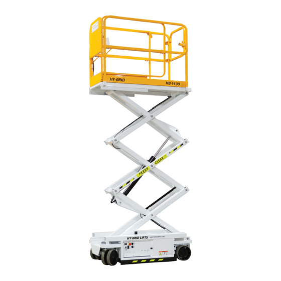
Self-propelled aerial work platform
Hide thumbs
Also See for II Series:
- Maintenance & troubleshooting manual (48 pages) ,
- Operation & safety manual (28 pages) ,
- Operation & safety manual (32 pages)

Related Manuals for Hy-Brid Lifts II Series


Summary of Contents for Hy-Brid Lifts II Series
- Page 1 BY CU STO M EQUIPMENT LLC OPERATIONS & SAFETY MANUAL SUPO-693 REV C SELF-PROPELLED AERIAL WORK PLATFORM HB-1030 HB-1430 SERIES II...
-
Page 2: Notes
NOTES If there is a question about application and/or operation, contact: Custom Equipment, LLC 2647 Hwy 175 Richfield, WI 53076 U.S.A. P: +1-262-644-1300 F: +1-262-644-1320 www.hybridlifts.com BY CUSTO M EQUIPMENT LLC OPERATIONS & SAFETY SUPO-693 HB-1030/HB-1430 REV C... -
Page 3: Foreword
FOREWORD Original instructions are written in English. The purpose of this Operations and Safety manual is to provide users with the instructions and operating procedures essential to properly and safely operate the Custom Equipment Hy-Brid Lift for its intended purpose, and to position personnel and their necessary tools and materials. -
Page 4: Table Of Contents
TABLE OF CONTENTS NOTES ......................................2 FOREWORD ....................................3 TABLE OF CONTENTS ................................4 INDEX OF FIGURES ..................................5 SECTION 1 | SAFETY .................................. 6 1.1 | SAFETY SYMBOLS ..................................6 1.2 | GENERAL RULES AND PRECAUTIONS ..........................6 1.3 | SAFETY FEATURES ..................................7 1.4 | SAFETY INDICATORS &... -
Page 5: Index Of Figures
INDEX OF FIGURES FIGURE 1: Pothole Guard ..................................7 FIGURE 2: Emergency Lowering Valve ..............................8 FIGURE 3: Down Instruction Decal No. DE600-29 ......................... 8 FIGURE 4: Maintenance Lock Pin use ..............................9 FIGURE 5: Maintenance Lock Pin storage ............................9 FIGURE 6: Decal Locations .................................. -
Page 6: Section 1 | Safety
SECTION 1 | SAFETY 1.1 | SAFETY SYMBOLS DANGER “DANGER” indicates an imminently hazardous situation, which, if not avoided, will result in death or serious injury. FAILURE TO FOLLOW THIS WARNING WILL CAUSE DEATH OR PERSONAL INJURY. WARNING “WARNING” indicates a potentially hazardous situation, which, if not avoided, could result in death or serious injury. -
Page 7: Safety Features
SECTION 1 | SAFETY 1.3 | SAFETY FEATURES • Puncture-Proof Wheels. • Guardrails—42 in (1.07 m) height with 4 in (10.16 cm) kick plates. • Non-Slip Deck. • Entrance Gate. • Automatic Parking Brake. • Free Descent Protection. A velocity fuse is installed in the hydraulic circuit to prevent the platform from descending in case of a ruptured hydraulic hose. -
Page 8: Maintenance Lock
SECTION 1 | SAFETY EMERGENCY LOWERING PUSH, TURN AND PULL KNOB FIGURE 3: Down Instruction Decal No. DE600-29 FIGURE 2: Emergency Lowering Valve WARNING IF PLATFORM SHOULD FAIL TO LOWER, DO NOT ATTEMPT TO CLIMB DOWN THE BEAM ASSEMBLY. SERIOUS INJURY MAY RESULT. HAVE AN EXPERIENCED OPERATOR USE THE EMERGENCY LOWERING PROCEDURE TO SAFELY LOWER THE PLATFORM. -
Page 9: Safety Guidelines
SECTION 1 | SAFETY FIGURE 4: Maintenance Lock Pin use FIGURE 5: Maintenance Lock Pin storage 1.7 | SAFETY GUIDELINES Only qualified operators may operate this unit. • All operators must read and understand the Operation and Safety Manual. They must understand all decals and warning labels on unit. -
Page 10: Proposition 65
SECTION 1 | SAFETY DANGER DO NOT OPERATE MACHINE NEAR POWER LINES. THE PLATFORM AND ENCLOSURES ARE NOT INSULATED. Equipment is only as safe as the operator. • Do not use ladders or scaffolding on the platform to obtain greater height. •... - Page 11 THIS PAGE WAS INTENTIONALLY LEFT BLANK BY CUSTO M EQUIPMENT LLC OPERATIONS & SAFETY SUPO-693 HB-1030/HB-1430 REV C...
-
Page 12: Section 2 | Product Description
SECTION 2 | PRODUCT DESCRIPTION 2.1 | GENERAL Custom Equipment’s Hy-Brid Scissors Lift is an aerial work platform designed to be safe and reliable. The purpose of the machine is to elevate personnel, along with their necessary tools and materials to overhead work locations. Manufacturer approval is required for any use other than the intended use. - Page 13 SECTION 2 | PRODUCT DESCRIPTION FLOOR LOADING HB-1030 HB-1430 Machine Weight (Unloaded) (Approx.) 1273 lb 577.4 kg 1645 lb 746 kg Minimum Wheel Load-Contact 62.7 psi 432.5 kPa Pressure 80.9 psi 557.6 kPa Maximum Wheel Load-Contact 99.3 psi 684.8 kPa Pressure 113.6 psi 783.0 kPa...
-
Page 14: Section 3 | Decals
SECTION 3 | DECALS 3.1 | DECAL LOCATION FIGURE 6: Decal Locations BY CUSTO M EQUIPMENT LLC OPERATIONS & SAFETY SUPO-693 HB-1030/HB-1430 REV C ITEM... -
Page 15: Decal Descriptions
SECTION 3 | DECALS 3.2 | DECAL DESCRIPTIONS ITEM # PART # DECAL MEANING OR DESIGNATION 112-21-218-50-K DECALS,HB-1030 112-21-218-55-K DECALS,HB-1430 DE707 DECAL,KEEP DE708 DECAL,CLEAR DE717-62 DECAL,SAFETY STRIPE (12.00) DE822 DECAL,WEBSITE DE600E-10 DECAL,MANUAL BOX DE709 DECAL, LWR DE600-28 DECAL,E-DOWN LOCATION DE600E-14 DECAL,MAINT LOCK DE600-29 DECAL,E-DOWN... -
Page 16: Decal Symbols
SECTION 3 | DECALS 3.3 | DECAL SYMBOLS • No Unauthorized Use • Do not operate this machine unless you have been trained in safe operation. • Training includes complete knowledge of the safety and operating instructions contained in the manufacturer’s manual, your employer’s work rules, and applicable government regulations. - Page 17 SECTION 3 | DECALS • Tip Hazard • Tip Hazard • Do not elevate platform on an incline or step. • Tip Hazard • Do not elevate platform on a slope. • Tip Hazard • Do not elevate platform on uneven or soft surfaces. •...
- Page 18 SECTION 3 | DECALS • Emergency Lowering • Battery disconnect • Fork pocket • Hydraulic oil level • Engaging mechanical Action: Enable Switch • Lanyard anchorage point location: Capacity 1 Person • Lanyard anchorage points are for work positioning restraints only, not for fall •...
- Page 19 THIS PAGE WAS INTENTIONALLY LEFT BLANK BY CUSTO M EQUIPMENT LLC OPERATIONS & SAFETY SUPO-693 HB-1030/HB-1430 REV C...
-
Page 20: Section 4 | Transport, Handling & Storage
SECTION 4 | TRANSPORT, HANDLING & STORAGE 4.1 | PRELIMINARY UNPACKING INSTRUCTIONS AND DEALER INSPECTION Maintenance locks must be engaged prior to inspecting or servicing the unit when the platform is elevated. Inspect machine for any possible damage during shipment; perform pre-delivery inspection. See checklist in the Maintenance Manual. -
Page 21: Fork Lift Pockets
SECTION 4 | TRANSPORT, HANDLING & STORAGE FIGURE 8: Fork Pockets FIGURE 9: Tie-Down Points 4.5 | FORK LIFT POCKETS Fork lift pockets are provided from the front and back of the unit for loading and unloading. A forklift from the side of the machine is not recommended. -
Page 22: Section 5 | Operation
SECTION 5 | OPERATION 5.1 | BEFORE YOU OPERATE Before use each day or at the beginning of each shift, the machine shall be given a visual inspection and functional test. Repairs (if any) must be made prior to operating the machine, as it is critical to ensure safe operation of the machine. -
Page 23: Startup/Shut Down
SECTION 5 | OPERATION 5.2 | STARTUP/SHUT DOWN DANGER THE OPERATOR MUST BE AWARE OF THE ENVIRONMENT. DO NOT RAISE THE PLATFORM IF THE MACHINE IS NOT ON A FIRM, LEVEL SURFACE. Operation Startup & Shutdown Practices • Check that the work area is safe. •... -
Page 24: Driving And Steering
SECTION 5 | OPERATION 5.3 | DRIVING AND STEERING WARNING CHECK THAT THE ROUTE OF TRAVEL TO BE TAKEN IS CLEAR OF PEOPLE, OBSTRUCTIONS, DEBRIS, HOLES, AND DROP-OFFS; AND IS CAPABLE OF SUPPORTING THE MACHINE. Always check front steer wheel direction before driving. If there is resistance in turning the casters while pivoting the machine, steer forward to allow the casters to straighten out before turning. -
Page 25: Extending The Platform
SECTION 5 | OPERATION 5.5 | EXTENDING THE PLATFORM Stand on the platform deck. 2. Grip the Slide Lock Handle (Figure 13) to allow the deck to slide. 3. Slide the deck out to one of two locking points, one at approximately 15 in (38 cm) extension, the other at approximately 30 in (76.2 cm) extension. -
Page 26: Daily Maintenance
SECTION 5 | OPERATION 5.6 | DAILY MAINTENANCE Regular inspection and conscientious maintenance is important to efficient economical operation of this machine. It will help to assure that equipment will perform satisfactorily with a minimum or service and repair. Make checks at the stated intervals or more frequently if required by local operating conditions. -
Page 27: Battery Displays
SECTION 5 | OPERATION 5.8 | BATTERY DISPLAYS This unit is equipped with one of several battery chargers. If the battery charger on this machine does not appear below, ther may be an additional manual addendum included in the manual box. CAUTION WARNING DO NOT OPERATE UNIT... -
Page 28: Figure 19: Lester Slm Battery Charge Indicator Location
SECTION 5 | OPERATION Battery Charge Indicators: Lester SLM (Charge Status indicated with Green light; Errors indicated with Red light) FIGURE 19: Lester SLM Battery Charge Indicator Location GREEN AMBER DESCRIPTION Charger is o and disconnected from live AC voltage (OFF) (OFF) (OFF) -
Page 29: Figure 20: Signet Battery Charge Indicator Location
SECTION 5 | OPERATION Battery Charge Indicators: Signet CHARGING STATE 100% 0-50% Charged Blinking Off 50-75% Charged Blinking Off 75-100% Charged Blinking NA 100% Charged Charge-Flooded Batteries FIGURE 20: Signet Battery Charge Charge-Sealed Batteries Indicator Location Abnormal Cycle Blinking NA Battery Charge Indicators: PCS/Dual Pro FIGURE 21: PCS/Dual Pro Battery Charge Indicator Location Battery 1 Status... -
Page 30: Section 6 | Pre-Start Inspection
SECTION 6 | PRE-START INSPECTION 6.1 | PRE-START INSPECTION CHECKLIST Pre-start Inspection (Self-Propelled Models) THIS CHECKLIST MUST BE USED AT THE BEGINNING OF EACH SHIFT OR CAUTION AFTER EVERY SIX TO EIGHT HOURS OF USE. FAILURE TO DO SO COULD AFFECT THE SAFETY OF THE OPERATOR. - Page 31 THIS PAGE WAS INTENTIONALLY LEFT BLANK BY CUSTO M EQUIPMENT LLC OPERATIONS & SAFETY SUPO-693 HB-1030/HB-1430 REV C...
- Page 32 2647 Highway 175 Richfield, WI 53076 U.S.A. Tel. + 262-644-1300 Fax. + 262-644-1320 www.hybridlifts.com service@customequipmentlifts.com “Hy-Brid Lifts” is a trademark of Custom Equipment, LLC. These machines comply with ANSI/SIA A92.6 and CSA B354.2-01 Revision Date: March 2019 Printed in the U.S.A.
Need help?
Do you have a question about the II Series and is the answer not in the manual?
Questions and answers