Table of Contents
Advertisement
Quick Links
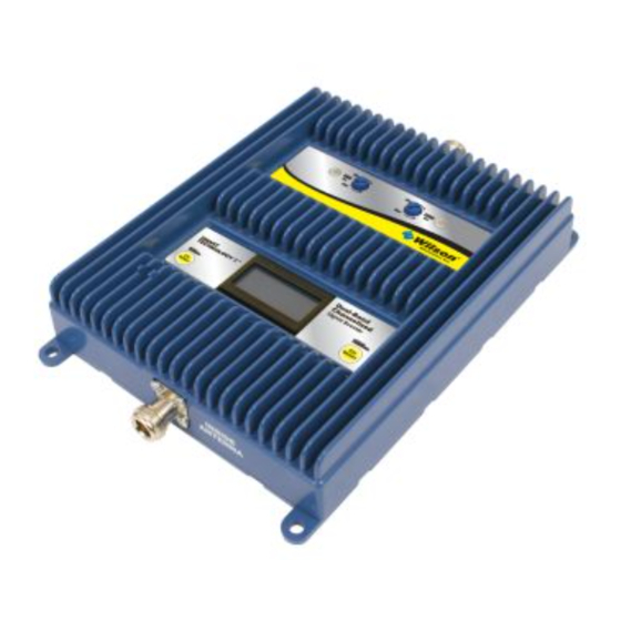
Dual-Band
Channelized
800 / 1900 MHz
Smart Technology ™
Signal Booster
Contents:
Antenna Options & Accessories . . . . . . . . . . . . . . . . . . . . . . . . . . . . . . . 1
Quick Install Overview . . . . . . . . . . . . . . . . . . . . . . . . . . . . . . . . . . . . . . . 2
Installation Diagram . . . . . . . . . . . . . . . . . . . . . . . . . . . . . . . . . . . . . . . . . 3
Before Getting Started . . . . . . . . . . . . . . . . . . . . . . . . . . . . . . . . . . . . . . . 4
Outside Antenna Installation . . . . . . . . . . . . . . . . . . . . . . . . . . . . . . . . . . 5
Finding the Strongest Signal . . . . . . . . . . . . . . . . . . . . . . . . . . . . . . . . . . 7
Installing the Inside Antenna . . . . . . . . . . . . . . . . . . . . . . . . . . . . . . . . . . 8
Installing a Wilson Electronics Signal Booster . . . . . . . . . . . . . . . . . . . . . 9
Powering up a Wilson Electronics Signal Booster . . . . . . . . . . . . . . . . . 10
Adjusting Channel & Gain . . . . . . . . . . . . . . . . . . . . . . . . . . . . . . . . . . . 11
Understanding the Signal Booster Lights & LCD Screen . . . . . . . . . . . 13
Warnings and Recommendations . . . . . . . . . . . . . . . . . . . . . . . . . . . . . 16
Guarantee & Warranty . . . . . . . . . . . . . . . . . . . . . . . . . . . . . . . . . . . . . . 18
Specifications . . . . . . . . . . . . . . . . . . . . . . . . . . . . . . . . . . . . Back Cover
Appearance of device and accessories may vary .
Note: This manual contains important safety and operating information . Please read and follow the
instructions in this manual . Failure to do so could be hazardous and result in damage to your Signal
Booster .
Advertisement
Table of Contents

Subscribe to Our Youtube Channel
Related Manuals for Wilson Electronics 277280


Summary of Contents for Wilson Electronics 277280
-
Page 1: Table Of Contents
Powering up a Wilson Electronics Signal Booster . . . . . . . . . . . . . . . . . -
Page 2: In-Building Wireless
. They amplify a weak or shadowed signal in mobile, M2M, marine and in-building applications . When using a Wilson Electronics Signal Booster in conjunction with Wilson Electronics antennas, the Outside Antenna will collect the cell tower signal and send it through the cable to the Signal Booster . -
Page 3: Quick Install Overview
Quick Install Overview See Installation Diagram on page 3 & 4 . Contact Wilson Electronics Technical Support Team with any questions at 866-294-1660 . Select a location to install the Signal Booster that is away from excessive heat, direct sunlight, moisture and has proper ventilation . Do not place the Signal Booster in an air-tight enclosure . -
Page 4: Installation Diagram
(sold separately). Make sure the protector is installed in line between the Outside Antenna and the Signal Booster. Power Supply Typical Installation Contact Wilson Electronics Technical Support Team with any questions at 866-294-1660 or email: tech@wilsonelectronics.com. Mon.- Fri. Hours: 7 am to 6 pm MST. -
Page 5: Before Getting Started
Before Getting Started This guide will help you properly install your Wilson Electronics Signal Booster . It is important to read through all of the installation steps for your particular application prior to installing any equipment. Read through the instructions, visualize where all the equipment will need to be installed and do a soft installation before mounting any equipment . -
Page 6: Outside Antenna Installation
. Position the antenna so that it has an unobstructed line of sight to the cell tower’s strongest signal . Make sure Contact Wilson Electronics Technical Support Team with any questions at 866-294-1660 or email: tech@wilsonelectronics.com. - Page 7 Note: Never point the front of a directional antenna toward the Inside Antenna. See Figures 1 & 2 on page 10. Contact Wilson Electronics Technical Support Team with any questions at 866-294-1660 or email: tech@wilsonelectronics.com. Mon.- Fri. Hours: 7 am to 6 pm MST.
-
Page 8: Finding The Strongest Signal
The closer you get to zero the stronger the signal . (See graph below) . Signal Strength Graph EXCELLENT GOOD POOR SIGNAL -50dB -60dB -70dB -80dB -90dB -100dB -110dB Contact Wilson Electronics Technical Support Team with any questions at 866-294-1660 or email: tech@wilsonelectronics.com. Mon.- Fri. Hours: 7 am to 6 pm MST. -
Page 9: Installing The Inside Antenna
75 feet of horizontal separation . Refer to installation diagram on pages 3 & 4 . Inside Antenna Ceiling Ceiling Drywall Rafters Contact Wilson Electronics Technical Support Team with any questions at 866-294-1660 or email: tech@wilsonelectronics.com. Mon.- Fri. Hours: 7 am to 6 pm MST. -
Page 10: Installing A Wilson Electronics Signal Booster
Warning: An Inside Antenna must have a separation distance from all persons that is at least 8 inches for the Panel Antenna . Contact Wilson Electronics Technical Support Team with any questions at 866-294-1660 or email: tech@wilsonelectronics.com. Mon.- Fri. Hours: 7 am to 6 pm MST. -
Page 11: Powering Up A Wilson Electronics Signal Booster
5 . Using multiple Signal Boosters in one installation could cause interference to the cell tower . 6 . Contact Wilson Electronics Technical Support Team with any questions at 866-294-1660 or email tech@wilsonelectronics .com . Technical Support hours are Mon .- Fri . 7 am to 6 pm MST . -
Page 12: Adjusting Channel & Gain
6 . Pressing the 800 MHz “CH Select” button steps between channels listed in Table 1 on page 15 . Contact Wilson Electronics Technical Support Team with any questions at 866-294-1660 or email: tech@wilsonelectronics.com. Mon.- Fri. Hours: 7 am to 6 pm MST. - Page 13 10 . If a red light or “OVERLOAD” is displayed on LCD screen, turn the 800 or 1900 MHz knob as shown in Figure 5 . Figure 5 1900 Contact Wilson Electronics Technical Support Team with any questions at 866-294-1660 or email: tech@wilsonelectronics.com. Mon.- Fri. Hours: 7 am to 6 pm MST.
-
Page 14: Understanding The Signal Booster Lights & Lcd Screen
Outside Antenna position until the “OVERLOAD” is replaced Gain Select Gain by the normal LCD screen . Contact Wilson Electronics Technical Support Team with any questions at 866-294-1660 or email: tech@wilsonelectronics.com. Mon.- Fri. Hours: 7 am to 6 pm MST. - Page 15 The indicator light on the Signal Booster will be a solid green after the first 15 minute installation period, if the unit is powered up and working properly . Contact Wilson Electronics Technical Support Team with any questions at 866-294-1660 or email: tech@wilsonelectronics.com. Mon.- Fri. Hours: 7 am to 6 pm MST.
- Page 16 5 .08 7 .7 7 .85 10 .1 12 .9 13 .2 15 .05 18 .35 18 .6 Contact Wilson Electronics Technical Support Team with any questions at 866-294-1660 or email: tech@wilsonelectronics.com. Mon.- Fri. Hours: 7 am to 6 pm MST.
-
Page 17: Warnings And Recommendations
Warning: Connecting the Signal Booster directly to the cell phone with use of an adapter will damage the cell phone and/or Signal Booster . Warning: Use only the correct Wilson Electronics power supply . Use of a non-Wilson Electronics product may damage your equipment . - Page 18 . However, no responsibility is assumed by Wilson Electronics, Inc . for any business or personal losses arising from its use, or for any infringements of patents or other rights of third parties that may result from its use .
-
Page 19: Guarantee & Warranty
About Wilson Electronics Wilson Electronics, Inc . has been a leader in the wireless communications industry for over 40 years . The company designs and manufactures Signal Boosters, antennas and related components that significantly improve cellular telephone signal reception and transmission in a wide variety of applications, both mobile (marine, RV, vehicles) and in-building (home, office, M2M) . -
Page 20: Specifications
Signal Booster Specifications Dual-Band Channelized 800 / 1900 MHz Model Number 277280 Antenna connectors N-Female Antenna Impedance 50 Ohms Dimensions 8 .875 x 6 .0 x 1 .5 inch (22 .5 x 15 .2 x 3 .8 cm) Weight 2 .8 lbs (1 .270 kg)
Need help?
Do you have a question about the 277280 and is the answer not in the manual?
Questions and answers