Table of Contents
Advertisement
Quick Links
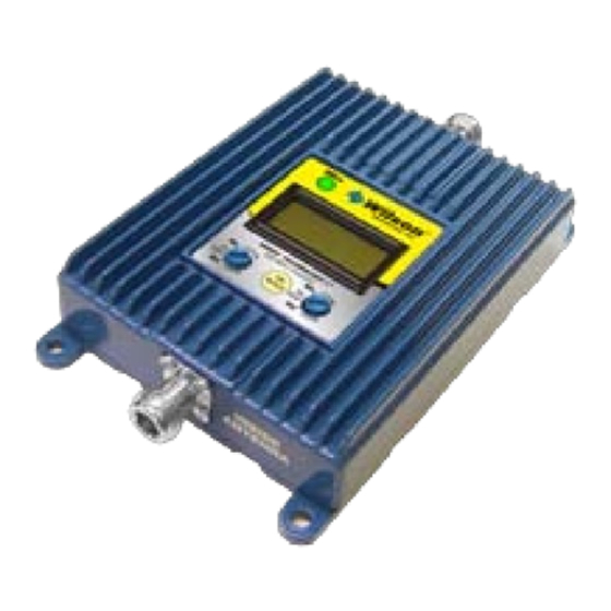
Channelized
800 MHz & 1900 MHz
Adjustable Gain
In-Building Wireless Smart Technology ™
Signal Boosters
Contents:
Antenna Options & Accessories . . . . . . . . . . . . . . . . . . . . . . . . . . . . . . . 1
Quick Install Overview . . . . . . . . . . . . . . . . . . . . . . . . . . . . . . . . . . . . . . . 2
Installation Diagram . . . . . . . . . . . . . . . . . . . . . . . . . . . . . . . . . . . . . . . . . 3
Before Getting Started . . . . . . . . . . . . . . . . . . . . . . . . . . . . . . . . . . . . . . . 4
Finding the Strongest Signal . . . . . . . . . . . . . . . . . . . . . . . . . . . . . . . . . . 5
Outside Antenna Installation . . . . . . . . . . . . . . . . . . . . . . . . . . . . . . . . . . 7
Installing the Inside Antenna . . . . . . . . . . . . . . . . . . . . . . . . . . . . . . . . . . 8
Installing a Wilson Electronics Signal Booster . . . . . . . . . . . . . . . . . . . . . 9
Powering up a Wilson Electronics Signal Booster . . . . . . . . . . . . . . . . . 10
LCD, Uplink & Downlink Directions . . . . . . . . . . . . . . . . . . . . . . . . . . . . 11
Understanding the Signal Booster Light & LCD Screen . . . . . . . . . . . . 12
Warnings and Recommendations . . . . . . . . . . . . . . . . . . . . . . . . . . . . . 15
Guarantee & Warranty . . . . . . . . . . . . . . . . . . . . . . . . . . . . . . . . . . . . . . 17
Specifications . . . . . . . . . . . . . . . . . . . . . . . . . . . . . . . . . . . . Back Cover
Appearance of device and accessories may vary .
Note: This manual contains important safety and operating information . Please read and follow the
instructions in this manual . Failure to do so could be hazardous and result in damage to your Signal
Booster .
Advertisement
Table of Contents

Related Manuals for Wilson Electronics 277380


Summary of Contents for Wilson Electronics 277380
-
Page 1: Table Of Contents
Powering up a Wilson Electronics Signal Booster . . . . . . . . . . . . . . . . . -
Page 2: Antenna Options & Accessories
To purchase, call Wilson Electronics Sales Department at: 800-204-4104 We recommend using directional antennas with these Signal Boosters . Contact Wilson Electronics Technical Support Team with any questions at 866-294-1660 or email: tech@wilsonelectronics.com. Mon.- Fri. Hours: 7 am to 6 pm MST. -
Page 3: Quick Install Overview
Quick Install Overview See Installation Diagram on pages 3 & 4 . Contact Wilson Electronics Technical Support Team with any questions at 866-294-1660 . Select a location to install the Signal Booster that is away from excessive heat, direct sunlight, moisture and has proper ventilation . Do not place the Signal Booster in an air-tight enclosure . -
Page 4: Installation Diagram
(sold separately). Make sure the protector is installed in line between the Outside Antenna and the Signal Booster. Power Supply Typical Installation Contact Wilson Electronics Technical Support Team with any questions at 866-294-1660 or email: tech@wilsonelectronics.com. Mon.- Fri. Hours: 7 am to 6 pm MST. -
Page 5: Before Getting Started
Before Getting Started This guide will help you properly install your Wilson Electronics Signal Booster . It is important to read through all of the installation steps for your particular application prior to installing any equipment. Read through the instructions, visualize where all the equipment will need to be installed and do a soft installation before mounting any equipment . -
Page 6: Finding The Strongest Signal
(between 10-30 seconds for phone to reset to the signal reading) . Contact Wilson Electronics Technical Support Team with any questions at 866-294-1660 or email: tech@wilsonelectronics.com. Mon.- Fri. Hours: 7 am to 6 pm MST. - Page 7 Note: Never point the front of a directional antenna toward the Inside Antenna. See Figures 1 & 2 on page 10. Contact Wilson Electronics Technical Support Team with any questions at 866-294-1660 or email: tech@wilsonelectronics.com. Mon.- Fri. Hours: 7 am to 6 pm MST.
-
Page 8: Outside Antenna Installation
. LSP sold separately, at www.WilsonElectronics.com or contact our sales team at 800-204-4104 . Signal Booster Surge Protector Power Strip Contact Wilson Electronics Technical Support Team with any questions at 866-294-1660 or email: tech@wilsonelectronics.com. Mon.- Fri. Hours: 7 am to 6 pm MST. -
Page 9: Installing The Inside Antenna
75 feet of horizontal separation . Refer to installation diagram on pages 3 & 4 . Inside Antenna Ceiling Ceiling Drywall Rafters Contact Wilson Electronics Technical Support Team with any questions at 866-294-1660 or email: tech@wilsonelectronics.com. Mon.- Fri. Hours: 7 am to 6 pm MST. -
Page 10: Installing A Wilson Electronics Signal Booster
AC Power Strip with at least a 1000 Joule rating. Failure to do this will void your warranty in the event of a power surge or lightning strike. Contact Wilson Electronics Technical Support Team with any questions at 866-294-1660 or email: tech@wilsonelectronics.com. Mon.- Fri. Hours: 7 am to 6 pm MST. -
Page 11: Powering Up A Wilson Electronics Signal Booster
5 . Using multiple Signal Boosters in one installation could cause interference to the cell tower . 6 . Contact Wilson Electronics Technical Support Team with any questions at 866-294-1660 or email tech@wilsonelectronics .com . Technical Support hours are Mon .- Fri . 7 am to 6 pm MST . -
Page 12: Lcd, Uplink & Downlink Directions
Uplink center frequency is the top number on the screen . It steps 2 .5 MHz every other time you push the “CH Select” button . Contact Wilson Electronics Technical Support Team with any questions at 866-294-1660 or email: tech@wilsonelectronics.com. -
Page 13: Understanding The Signal Booster Light & Lcd Screen
UL CH DL Blinking will stop after the 15 minute installation period . 70 A 72 Contact Wilson Electronics Technical Support Team with any questions at 866-294-1660 or email: tech@wilsonelectronics.com. Mon.- Fri. Hours: 7 am to 6 pm MST. 800 MHz Channel... - Page 14 “OVERLOAD” is 1900 MHz Channelized replaced with “UL CH DL .” Gain Select Gain Contact Wilson Electronics Technical Support Team with any questions at 866-294-1660 or email: tech@wilsonelectronics.com. Mon.- Fri. Hours: 7 am to 6 pm MST.
- Page 15 The indicator light on the Signal Booster will be a solid green after the first 15 minute installation period, if the unit is powered up and working properly . Contact Wilson Electronics Technical Support Team with any questions at 866-294-1660 or email: tech@wilsonelectronics.com. Mon.- Fri. Hours: 7 am to 6 pm MST.
- Page 16 -45 dB BW MHz (BW) MHz 5 MHz 5 .08 7 .7 7 .85 15 .05 18 .35 18 .6 Contact Wilson Electronics Technical Support Team with any questions at 866-294-1660 or email: tech@wilsonelectronics.com. Mon.- Fri. Hours: 7 am to 6 pm MST.
-
Page 17: Warnings And Recommendations
(1) This device may not cause harmful interference, and (2) this device must accept any interference received, including interference that may cause undesired operation . Changes or modifications not expressly approved by Wilson Electronics could void the authority to operate this equipment . -
Page 18: Guarantee & Warranty
About Wilson Electronics Wilson Electronics, Inc . has been a leader in the wireless communications industry for over 40 years . The company designs and manufactures Signal Boosters, antennas and related components that significantly improve cellular telephone signal reception and transmission in a wide variety of applications, both mobile (marine, RV, vehicles) and in-building (home, office, M2M) . - Page 19 . However, no responsibility is assumed by Wilson Electronics, Inc . for any business or personal losses arising from its use, or for any infringements of patents or other rights of third parties that may result from its use .
-
Page 20: Specifications
Signal Booster Specifications Channelized 800 Channelized 1900 Model Number 277180 277380 Antenna connectors N Type N Type Antenna impedance 50 Ohms 50 Ohms Dimensions 6 .75 x 4 x 1 .3 inch (17 .1 x 10 .2 x 3 .3 cm) 6 .75 x 4 x 1 .3 inch (17 .1 x 10 .2 x 3 .3 cm)
Need help?
Do you have a question about the 277380 and is the answer not in the manual?
Questions and answers