
Related Manuals for Wilson Electronics weboost Office 200


Summary of Contents for Wilson Electronics weboost Office 200
- Page 1 A WILSON ELECTRONICS BRAND Cell Signal Booster Installation Guide https://www.signalbooster.com 855.846.2654 NEED HELP?
- Page 2 ______ Index Package Contents Preparation Inside Antenna & Booster Placement STEP 1: Mount Outside Antenna STEP 2: Route & Connect Outside Antenna To Booster STEP 3: Route & Connect Inside Antenna To Booster STEP 4: Power Up The Booster STEP 5: Measuring Booster Performance Menu System Troubleshooting...
- Page 3 ______ Package Contents Office 200 Inside Outside 75’ & 60’ 2’ Wilson 400 Booster Antenna Antenna Wilson 400 Cables Cable (314407) (314422) (952360 & 952375) (952302) Power Lightning Surge Cable Mounting Supply Protector Clips (850026) (859902) Office 200 Inside Outside 75’...
-
Page 4: Key Features
______ Key Features Extended Dynamic Range (XDR) for continuous connectivity: any incoming signal and never shuts down due to a strong outside signal. Simple Wall-Mount Installation: An indoor and outdoor port are located on top of the amplifier for easy antenna connections, while an exposed mounting flange at each corner of the amplifier provides for simple and clean wall- mount installation. - Page 5 ______ Preparation You Will Need (tools not included) Make sure the following materials are prepared and ready for your installation. 1 to 2 hours Ladder Drill 1” - 2” diameter existing pole for mounting Outside Antenna (#901117 Pole Mount can be purchased separately if needed) Recommended: Power Strip with surge protection OFFICE 200...
-
Page 6: Installation Diagram
______ Installation Diagram 60 FEET HORIZONTAL OR 25 FEET VERTICAL DISTANCE Troubleshooting section recommends increasing distance further if needed. Outside Antenna 75’ Coax Cable Lightning Surge Protector 60’ Coax Cable Inside Antenna Booster to power OFFICE 200 CELL PHONE SIGNAL BOOSTER... - Page 7 ______ Step 1: Inside Antenna & Booster Placement Place the inside antenna in the ceiling over where you need the greatest signal boost and place booster in your desired location at least 24” away from inside antenna. NOTE: Do not connect booster to power until the system is fully installed. drywall ceiling mount Plastic Nut...
-
Page 8: Step 2: Mount Outside Antenna
______ Step 2: Mount Outside Antenna Pole mounting and wall mounting options are included. Attach the mount to the outside antenna and use the bracket clamp to attach the antenna to a pole or exhaust pipe. Outside Antenna L-Bracket U-Bolt Pole Bracket existing... - Page 9 ______ Step 3: Route & Connect Outside Antenna To Booster Connect 2 ft. coax cable to outside antenna, attach the lightning surge protector, then connect the black 75 ft. coax cable and route into building. Outside Cable Mounting Clips Lightning Surge Antenna provided Protector...
- Page 10 ______ Step 4: Route & Connect Inside Antenna To Booster Connect the black 60 ft. coax cable to inside antenna and route to the 200 booster and connect to the port labeled ‘INSIDE ANTENNA’. Cable Mounting Clips provided 60’ Coax Cable Inside Antenna Booster...
-
Page 11: Step 5: Power Up The Booster
______ Step 5: Power Up The Booster Plug the power supply into wall outlet then connect to end of booster labeled “ ” and enjoy your boosted signal. NOTE: We strongly recommend using a power strip with surge protection. to power 60 FEET HORIZONTAL OR 25 FEET VERTICAL DISTANCE Troubleshooting section recommends increasing distance further if needed. -
Page 12: Measuring Booster Performance
______ Measuring Booster Performance How To Get Signal Strength As A Number iPhone® iOS 11 and later no longer displays the decibel (dBm) reading in ‘Field Test Mode’. Tip: Using the signal bars and performing data speed tests on your cell phone can assist you in finding locations. - Page 13 ______ (MEASURING BOOSTER PERFORMANCE cont.) Signal Strength without Booster Note here: Signal Strength with Booster Note here: Compare Results Having an accurate measurement of signal strength in decibel-milliwatts (dBm) is crucial when installing your system. dBm accurately measure the signal strength you are receiving. EXCELLENT GOOD FAIR...
-
Page 14: Menu System
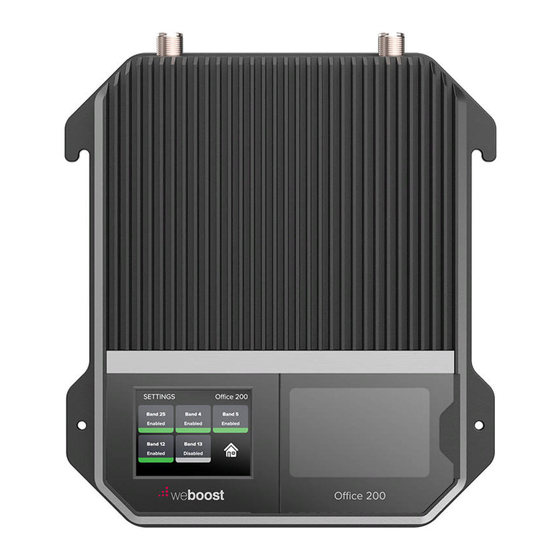
______ Menu System screen will appear, showing the amplification and status of each port and band. Home Screen Start Up Screen Band Menu Color Desrciption GREEN: A solid green light indicates that a band is operating correctly with maximum allowable gain. YELLOW: A solid yellow light indicates band gain reduction because of an oscillation condition. - Page 15 Settings Screen Tap icon to view the Settings Screen. Bands can be disabled/enabled by tapping the desired band. Note: disabling a cell band is not recommended. Bands should only be disabled by expert installers. OFFICE 200 CELL PHONE SIGNAL BOOSTER...
- Page 16 To go back to the home screen tap on the home icon. To view specific band information (such as the strength of the received uplink & downlink signal, status details and the amplifier gain) tap desired band on the home screen.
- Page 17 By tapping on the desired Band, a more detailed screen will appear for better troubleshooting. Note: If the reduced gain due to oscillation is greater or equal to 60dB, this condition will be displayed as Green instead of Yellow and no action is necessary. OFFICE 200 CELL PHONE SIGNAL BOOSTER...
-
Page 18: Troubleshooting
______ Troubleshooting IF YOU ARE HAPPY WITH THE COVERAGE, THESE LIGHT ISSUES DON’T HAVE TO BE RESOLVED. YOUR CARRIER’S BAND HAS NOT BEEN AFFECTED. If the bands are any color other than green, use the touchscreen LCD and tap any given band that’s not green to see troubleshooting options. https://www.signalbooster.com 855.846.2654 NEED HELP? -
Page 19: Safety Guidelines
______ Safety Guidelines Use only the power supply provided in this package. Use of a non-weBoost power supply may damage your equipment. The signal booster unit is designed for use in an indoor, temperature-controlled environment (less than 100 degrees Fahrenheit). It is not intended for use in attics or similar locations subject to temperatures in excess of that range. -
Page 20: Antenna Kit Options
______ Antenna Kit Options BAND 13 BAND 5 BAND 25/2 BAND 12/17 BAND 4 Outside antenna maximum permissible antenna gain (dBi) 50 Inside antenna maximum permissible -0.4 -0.1 -0.7 antenna gain (dBi) 50 FIXED INSIDE ANTENNA KIT OPTIONS Kit # Coax Type Ln(ft) Antenna Type... -
Page 21: Specifications
______ Specifications Office 200 ™ Model Number 460047 FCC ID PWO460047 Connectors N-F emale / F-Female Antenna Impedance 50 Ohms / 75 Ohms Frequency 698-716 MHz, 729-756 MHz, 777-787 MHz, 824-894 MHz, 1850-1995 MHz, 1710-1755/2110-2155 MHz 1700 1900 Power output for single cell Band12/17 Band13 Band 5... - Page 22 3 YEAR WARRANTY weBoost Signal Boosters are warranted for three (3) years against defects in workmanship and/or materials. Warranty cases may be resolved by returning the product directly to the reseller with a dated proof of purchase. Signal Boosters may also be returned directly to the manufacturer at the consumer’s expense, with a dated proof of purchase and a Returned Material Authorization (RMA) number supplied by we oost.
- Page 23 Notes https://www.signalbooster.com 855.846.2654 NEED HELP? OFFICE 200 CELL PHONE SIGNAL BOOSTER...
- Page 24 855.846.2654 https://www.signalbooster.com order@signalbooster.com Copyright © 2021 weBoost. All rights reserved. weBoost products covered by U.S. patent(s) and pending application(s) GDE000415_Rev01_05.20.21...
Need help?
Do you have a question about the weboost Office 200 and is the answer not in the manual?
Questions and answers