Table of Contents
Advertisement
Quick Links
Advertisement
Table of Contents

Subscribe to Our Youtube Channel
Related Manuals for Hobby FIAT Premium Drive


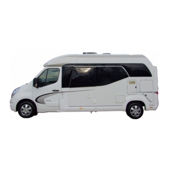
Summary of Contents for Hobby FIAT Premium Drive
- Page 1 PREMIUM VAN ANNIVERSARY EDITION • PREMIUM DRIVE MANUAL Version 10/2014...
- Page 2 Introduction Dear Camper, Congratulations on the purchase of your new HOBBY motor home. The trust you have placed in us is both an incentive and an obligation to continuously implement new ideas, technical innovations and fine touches to make our motor homes even better. Our fully fitted and highly sophisticated models enable us to offer you the perfect setting for the most enjo- yable days of the year.
-
Page 3: Table Of Contents
Introduction 00-1 Chapter 1: Introduction Chapter 4: Wheels, tyres General information ..........01-1 Wheels ..............04-1 Designations in the operating instructions ..... 01-2 Tyres ............... 04-1 Tyre pressure ............04-2 Chapter 2: Safety Tread depth ............04-2 General information ..........02-1 Wheel rims ............. - Page 4 Introduction 00-2 6.11 Construction of the seats ........06-24 10.7 Fume Hood ............10-29 6.12 Seatbelts in the motor home ........ 06-25 10.8 Rooftop Air Conditioning ........10-30 6.13 Overview of the seating arrangements ....06-26 Chapter 11: Accessories ..........11-1 Chapter 7: Electrical Installations Chapter 12: Maintenance and Care Safety instructions ..........
-
Page 5: Chapter 1: Introduction
For this reason, no • Please ensure that all of the deadlines for checking claims may be asserted against HOBBY based on the conten- equipment and inspections are met. ts of this user manual. Those accessories that are available at the time of going to print are described here. -
Page 6: Designations In The Operating Instructions
Introduction 01-2 1.2 Designations in the operating instructions Handling instructions Handling instructions are also given in the form of key words beginning with the symbol “•“. This manual explains the motor home in the following manner: Notes Texts and illustrations Texts that refer to illustrations are found directly below the Notes point out important details that ensure your motor illustrations. - Page 7 Introduction 01-3 Optional Extras You have selected a mobile home that is equipped to taste. This user manual describes all of the models and equipment offered within the same programme. Therefore, it may include equipment that you have not selected. Differences and, thus, all of the optional extras are marked with an asterisk „...
- Page 8 Introduction 01-4...
-
Page 9: Chapter 2: Safety
02-1 Safety Chapter 2: Safety 2.2 Fire protection Precautions against fire 2.1 General information • Never leave children alone in the vehicle. • Keep inflammable materials away from all heating and coo- • Operating and user instructions for built-in equipment (re- king devices. -
Page 10: Equipment
Safety 02-2 2.3 Equipment 2.3.1 Emergency equipment To be prepared in case of an emergency, you should always carry the three emergency devices on board and familiarize yourself with them. First-aid kit 100 m The first-aid kit should always be at hand and have a fixed position in your motor home. -
Page 11: Vehicle Tool Kit
02-3 Safety 2.3.2 Vehicle tool kit Renault: The tool box is included separately in the external storage locker. Each vehicle comes with individual basic equipment including a vehicle tool kit and accessories: Fiat: The tool box is located underneath the bed or in the external storage locker (model-specific). -
Page 12: Before Driving
You must show the following when applying for registration: If you have any further questions or difficulties, your autho- rised Hobby dealer will always be available to assist you! registration document, Part II / CoC insurance coverage • Tighten the nuts on the wheels after driving the first proof of personal identity or confirmation of registration by a 50 miles with your camper. -
Page 13: Before Each Drive
02-5 Safety 2.4.2 Before each drive Road safety • Before driving, check that the signalling and lighting systems (switch on battery circuit breaker), steering and brakes function correctly. • If the vehicle has been standing for a longer period of time (approx. - Page 14 Safety 02-6 Rear garage (model-specific) Battery When loading the rear garage adhere to the permissible axle • Fully charge the batteries before each journey. Please refer loads and the technically permissible total mass. Distribute pay- to the section on "Ancillary battery". load evenly.
- Page 15 02-7 Safety • Secure the table and, if possible, lower it. • If necessary remove the 230 V electric cable from the exte- • Close doors (including refrigerator door), drawers and rior socket. flaps firmly. • If necessary, slide the TV antenna in as far as possible or •...
-
Page 16: While Driving
02-8 Safety • Only install children's car seats on seats that have been fitted by the manufacturer with three-point belts. • Turn the swivel seats in the direction of traffic and lock them into place. The seats may not be turned while dri- ving. - Page 17 02-9 Safety Braking • Long descents with a slight gradient can become dangerous. Adjust your speed from the very beginning to allow you to The following applies for braking: speed up if necessary without endangering other automobiles. • Not the longer braking distance, especially on wet roads. •...
-
Page 18: After Driving
Safety 02-10 2.6 After driving Switching electric consumption: Selecting a parking space The following applies when switching electric consump- tion: The following applies for selecting a parking space: • Switch the refrigerator from 12 V to accelerator or 230 V. •... -
Page 19: Chapter 3: Chassis
In addition, the VIN is also given on the type plate of the base vehicle as well as on the Hobby type plate (in the motor compartment on the upper front cross member of the radiator). -
Page 20: Loading
Chassis 03-2 3.3 Loading Overloading can cause the tyres to break down or even burst! This increases the danger that you may lose control 3.3.1 General information of the vehicle. Therefore, you endanger yourself and other road users. Rules for loading: •... - Page 21 1. Technically permissible overall mass Number of built-in gas regulators: Information regarding the technically permissible maximum Weight of an 11 kg aluminium bottle: weight is based on Hobby Wohnwagenwerk's specification in Weight of 11 kg gas inflation: cooperation with the manufacturers of the previous construc- tion stages (Fiat, Renault). This mass takes into account the...
- Page 22 These optional extras will be shown in the actual mass of and kitchen fittings, food, camping equipment, toys, pets). the vehicle if − they are not part of the standard scope of equipment, The remaining additional load (5.) must always be greater than − Hobby or the manufacturer of the base vehicle were re- or equal to the minimum loading capacity (6.); this must be taken into account when determining the configuration of the vehicle. sponsible for assembling them, − the customer can order them.
-
Page 23: Leveling Supports
03-5 Chassis 3.4 Levelling supports Retracting levelling supports • Use crank to release levelling supports. • Continue to crank smoothly until the levelling support is once The levelling supports are located in the rear area by the again in its initial horizontal position. frame extension. - Do not use the levelling supports as a car jack. Their sole Swinging out the levelling supports purpose is to stabilise the motor home when it is parked. -
Page 24: Entrance Step
Chassis 03-6 3.5 Entrance step To open • Press the switch in the entrance area. The entrance step will be extended automatically. The motor homes are equipped with an electrically extenda- ble entrance step To close • Press the switch in the entrance area. Do not step on the entrance step until it has been comple- The entrance step will be retracted automatically. -
Page 25: Additional Pneumatic Springs
Chassis 03-7 The optimum air pressure is achieved when the vehicle is standing horizontally. The minimum air pressure must be high enough to ensure that the air bellows cannot snap through. When the vehicle is empty this pressure is approx. 0.5 bar (please check individually);... -
Page 26: Towing Fixture
Chassis 03-8 Please ensure that the permissible tow bar load, maximum towing weight and rear axle load for the vehicle are not exceeded, especially when you are loading the rear garage. Simultaneous use of the tow-bar and the rear carrier and/or eBike carrier is not permitted. While manoeuvring to hitch and unhitch loads, ensure that no-one is standing between the motor home and the trailer. -
Page 27: Externally Mounted Fixtures
03-9 3.8 Externally mounted fixtures 3.9 Automatic transmission Registering accessories in the vehicle's documents As an option, your motor home can be equipped with an au- • Have your HOBBY dealer mount your externally mounted tomatic transmission (Fiat: Comfort-Matic; Renault: Quickshift) fixtures. which has two methods of operation: MANUAL/gearshift and • Take your motor home to a technical support organisation AUTO(MATIC). Since the clutch is engaged and released by or technical service provider (e.g. - Page 28 Chassis 03-10 These three positions are not fixed, i.e. after the lever has been • Move the lever in the direction of (+) to shift up or in the moved it jumps back to the centre position. direction of (-) to shift down. Do not let go of the gas pedal while you are shifting gears.
- Page 29 Chassis 03-11 Never leave the vehicle when the transmission is in neutral (N). If the vehicle is not moving and you have already shifted into gear, always step on the brake pedal until you have decided to start driving. Only then should you release the brake pedal and slowly step on the gas pedal.
- Page 30 Chassis 03-12...
-
Page 31: Chapter 4: Wheels, Tyres
• Never drive an overloaded vehicle. be checked regularly to ensure that they fit tightly. Tubeless tyres have been mounted on your HOBBY motor Tightening torque for wheel nuts and bolts: home. Under no circumstances may tubes be inserted in... -
Page 32: Tyre Pressure
04-2 Wheels and tyres Snow chains Never drive faster than 50 km/h. Do not use snow chains on snow-free roads. Snow chains can only be mounted to tyres that are just as large as the tyres originally mounted on your vehicle. Snow chains may only be mounted on the front drive wheels;... -
Page 33: Tread Depth
04-3 Wheels and tyres 4.5 Wheel rims If the pressure is too low, this may cause overheating of the tyre, possibly resulting in severe damage to the tyre. Only use the rims noted in the registration documents. Should you wish to use other rims, please note the following. For the correct inflation pressure, please refer to the table in the chapter on “Technical Data“... -
Page 34: Fast Tyre Repair Kit
Wheels and tyres 04-4 The fast tyre repair kit can be used when the outside tempera- ture ranges from -20°C to + 50°C. Please refer to the FIAT or RENAULT manual for instruc- tions on how to use the fast tyre repair kit. There is an expiry date on the sealant. -
Page 35: Changing A Tyre
04-5 Wheels and tyres 4.7 Changing a tyre • Remove the wheel mounting screws and lift off the tyre. • Place the spare tyre (not included in the scope of delivery) on the wheel hub and align it. The car jack (not included in the scope of delivery) may only be inserted in the appropriate mounting holes! If •... - Page 36 Wheels and tyres 04-6...
-
Page 37: Chapter 5: Exterior Structure
05-1 Exterior Structure Chapter 5: Exterior Structure 5.1 Ventilation The following applies for ventilation: Ventilation is important if you want to feel comfortable in your motor home. No-draught ventilation has been integrated abo- ve the driving unit in your motor home. The roof lights ensure ventilation. - Page 38 Exterior Structure 05-2 Ventilation for the refrigerator on the roof of We recommend that you remove the ventilation grate if the vehicle the outside temperature is very high. This allows more air to permeate to the refrigerator, intensifying refrigeration. The ventilation grids must remain firmly mounted while driving or when it is raining.
-
Page 39: Opening And Closing Doors And Flaps
05-3 Exterior Structure 5.2 Opening and closing doors and flaps Keys to the vehicle The following keys are delivered with the motor home: two keys to fit the following locks on the base vehicle: - driver‘s and passenger‘s doors - a code card. Note the manufacturer‘s operating instructions for the basic vehicle. - Page 40 Exterior Structure 05-4 To prevent damage to locks and door frames, the inner door handle must be positioned horizontally and not slanted upwards. The entrance door is your escape route in an emergency. Never barricade the door from the outside! Entrance door external Opening •...
- Page 41 05-5 Exterior Structure Entrance door internal Insect screen (plissé) • Carefully open and close the insect screen plissé by gui- Opening ding it along the guide rail. • Push the bolt down (green section The insect screen plissé must be closed first before clo- Closing sing the entrance door! •...
- Page 42 Exterior Structure 05-6 The maximum load for the external storage locker is 150 kg. Garage flap/ Stowage flap (model-specific) To open • Unlatch both locks with the key. The handles will be slightly projected. • Turn the handle to the left. •...
- Page 43 05-7 Exterior Structure Toilet flap Gas-bottle Container Flap The ventilation grill of the gas-bottle container flap must To open not be closed or covered. • Use key to unlock flap • Press both buttons ( ) and open flap. To open •...
- Page 44 Exterior Structure 05-8 Locking devices for doors and flaps Flap locks • Open the gas-bottle container flap all the way. The entrance door as well as some of the external flaps can be • Lift open the locking device. fastened using the locks on the outside wall of the mobile home. •...
- Page 45 05-9 Exterior Structure Exterior gas supply Exterior socket The external gas socket is used to provide equipment Opening that requires gas, such as a gas barbecue or gas lamp, with • Take hold of the bottom of the cover flap and pull it up- gas outside the mobile home.
- Page 46 05-10 Exterior Structure Fresh water filler neck Petrol filler neck Opening The black petrol cap is covered by a flap located on the left • Hold the flap by the latch and pull it up. side of the vehicle behind the driver's door in the lower sec- •...
-
Page 47: Roof Rail
Exterior Structure 05-11 5.3 Roof rail The following applies when loading the roof rail: • Only store light items of luggage on the roof. • Lash the roof load securely and ensure that it cannot slip or fall off. • Do not overload the roof! The heavier the roof load, the worse the vehicle’s performance. -
Page 48: Bicycle Carrier
Exterior Structure 05-12 5.6 Velo eBike Carrier 5.5 Bicycle carrier The driver of the vehicle is responsible for ensuring that The motor home’s handling when driving is significantly the load has been fastened securely. This means that the different when the bicycle carrier is in use. The driving speed bicycles must be doubly secured on the carrier. -
Page 49: Sun Awning
05-13 Exterior Structure • Always maintain the permissible load-carrying capacity of the carrier (75 kg) and never overload it. • If the rear carrier is fully loaded, and depending on how much the load juts out over it, the load on the rear axle will be increased while it will be decreased on the front axle. - Page 50 Exterior Structure 05-14 Extending If the canvas is slack when extended, retract the awning • Insert the hook on the crank into the grommet on the win- until the canvas is tightly stretched again. ding mechanism. • Hold the crank with one hand on the upper twist grip and Please refer also to the manufacturer's separate operating the other on the lower twist grip.
-
Page 51: Chapter 6: Interior Structure
06-1 Interior Structure Chapter 6: Interior Structure 6.1 Opening and closing doors and flaps Close all flaps and doors properly before driving. This avoids them opening accidentally while driving and objects falling out. Stowage cabinets To open • Slightly tilt the handle and then pull on it until the flap opens. To close •... - Page 52 06-2 Interior Structure Drawers with a pressure lock Furniture doors with handle To open • Push the handle to open and shut the door. • Press the bottom of the pushbutton to unlock the drawer. • Pull on the handle until the pull-out opens. To close •...
- Page 53 06-3 Interior Structure Doors with push locks Furniture doors with a locking mechanism (Mirror cabinets, washroom) To open • Depress the push lock until the knob pops out. To open • Carefully pull the knob and open the door. • Open the door of the mirror cabinet by pressing the lower edge from behind.
- Page 54 06-4 Interior Structure Sliding doors Bar in the entrance area To open To open • Hold the sliding doors by the frame and push outward. • Pull on the handle and swing the door outwards. To close To close • Grasp the frame of the doors and push them closed until •...
-
Page 55: Mount For Flat Screen Tv
Interior Structure 06-5 6.2 TV mount for flat screen TV 6.3 Tables Luxury Living Room Table, • To fold out the mount, release the lock by pushing the lever to the right. The luxury living room table can be lowered as well as moved. •... - Page 56 Interior Structure 06-6 Hanging table To lower • Pull the lever all the way to the other side to unlock the When lowered, the hanging table can be used as a base frame table. for the bed. • Use both hands to push the table top down. To lower •...
-
Page 57: Bed Conversion
Interior Structure 06-7 6.4 Bed conversion • Hook the table top into the lower wall bracket . The lock must move up to lock into place and place the table on the The seating arrangements can be rearranged as beds for slee- shortened leg ping. - Page 58 Interior Structure 06-8 Widening the beds Fiat Drive • Insert the additional cushion In those models with individual beds above the rear garage, the two beds can be joined by means of an extendable extension. • Open both pushlocks • Pull out the extension as far as it will go.
- Page 59 06-9 Interior Structure Alcove berth (model-specific) Widening the beds Renault Premium Van Depending on the model, your vehicle may be equipped with • Release the extension from the magnet and pull it along the an alcove berth as an additional sleeping area. guide rail.
- Page 60 06-10 Interior Structure • Place the key in the alcove bed panel and turn it to the • Hang the ladder (located in the garage when your right to “on”. camper is delivered). • Use the arrow down to lower the alcove bed as far as it will •...
- Page 61 06-11 Interior Structure The stowage cabinets under the alcove bed should only be loaded lightly. The more weight stowed in these cabinets, the harder it is for the alcove bed motor to run. • The maximum load for the alcove berth is approx. 200 kg. •...
-
Page 62: Cushion Arrangements
Interior Structure 06-12 6.5 Cushion arrangements Rearranging the cushions Renault 65 GE Premium Van None of the motor homes with alcove beds can be con- verted, because there is not enough free space when the alcove bed has been lowered. Additional cushion 960x460x110... - Page 63 Interior Structure 06-13 Rearranging the cushions Fiat 70 GE Premium Drive Additional cushion 1110x540x110 6.6 Washroom with movable basin for showering (model-specific) Using the shower • Pull the handle on the washbasin along the rail towards the Porta Potti. • Then release the pushbutton of the retaining strap and fold out the partition towards the mirror When driving, the shower partition must be fastened using the retaining strap and the washbasin must notice-...
- Page 64 Interior Structure 06-14 Bathroom (model-specific) In Hobby's bathroom concept, the washroom can be joined together with the separate shower or changing room. • Open the washroom door as far as possible so that the iron core of the locking mechanism attaches itself to the magnet on the opposite side.
- Page 65 Interior Structure 06-15 Folding seat in the shower (optional extra) When driving, the doors of the separate shower must be As an option, the bathroom can be fitted with a folding seat in fastened using the retaining strap. the shower. •...
-
Page 66: Windows
Interior Structure 06-16 Fully adjustable window stays 6.7 Windows Knockout windows with locking hooks To open • Turn all latches by 90°. Opening • Press the window latch outwards with your hand until it is • Turn the latch by 90°. open as far as you would like. - Page 67 06-17 Interior Structure To combine • Pull the sunshade down slowly and evenly, then pull the insect screen down to the desired position. To avoid consequential damage, leave the shades open when the motor home is not in use. Combined sunshade and insect screen Sunshades and insect screens are integrated in the window from and fully adjustable.
-
Page 68: Dimming System For Driver's Cabin
Interior Structure 06-18 Skylight 6.8 Dimming system for driver's cabin (Acrylic glass frames cannot be supplied if the The dimming shades may only be drawn when the vehicle is roof window is above an alcove bed.) standing and the motor has been turned off. Before starting your drive, you must fold up the entire system and lock it. - Page 69 06-19 Interior Structure Front system Side system • Press the locks together to open the locking mecha- • Press the locks together to open the locking mecha- nism. nism. • Press the clasp together in the middle. The magnetic lock •...
-
Page 70: Skylight
06-20 Interior Structure 6.9 Skylight Safety instructions • Never open the skylight in strong winds/rain/hail, etc. or if the temperature outside is below -20°C! • Do not use force to open the roof skylight when covered by ice or snow as this could break the hinges and opening mechanism. - Page 71 Interior Structure 06-21 Insect screens and shades (plissés) Both plissés are fully adjustable by sliding them horizontally from side to side. Small roof bonnet Opening • This roof bonnet can be opened in the opposite direction to traffic. Press the locking knob and use the adjusting lever to move the roof bonnet to the desired position.
-
Page 72: Pivoting Seats In The Driver's Cab
Interior Structure 06-22 Swivelling seats • Put the armrests up. • Move the seat to the middle position. • Release the lever to swivel the seat. The seat will be relea- sed from the locking position. • Push the seat belt buckle down to avoid damaging it. •... - Page 73 Interior Structure 06-23 Renault Premium Van Fiat Premium Drive • The lever for turning the seat is located on the front • The lever for turning the seat is located on the outer edge of the seats in the driver's cab. Tilt the lever upwards edge of the seats in the driver's cab.
-
Page 74: Construction Of The Seats
Interior Structure 06-24 6.11 Construction of the seats Converting the L-shaped seating arrangement Cushion fastenings To use the outer seats in models with an L-shaped seating arrangement, it must be converted before you drive. The seat and back cushions are held in place by an anti-slip mat. -
Page 75: Seatbelts In The Motor Home
06-25 Interior Structure • Guide the upper part of the seatbelt over your shoulder and diagonally across your chest. • The lower part of the seatbelt fits across your hips. Unbuckling the seatbelt • Press the button on the lock of the seatbelt to unlock the tongue. -
Page 76: Overview Of The Seating Arrangements
Interior Structure 06-26 6.13 Overview of the seating arrangements Fiat 65 HFL Premium Drive Renault 65 GE Premium Van Seats 1 - 4: may be used while driving. Seats 1 - 4: may be used while driving. Seat 5: must not be used while driving. Seats 5 - 6: must not be used while driving. - Page 77 Interior Structure 06-27 Fiat 70 HGE Premium Drive Seats 1 - 3: may be used while driving Seat 4: may be used while driving if the permissible maximum weight = 3650kg / 4250kg / 4400kg Seat 5: must not be used while driving. Fiat 70 HQ Premium Drive Seats 1 - 3: may be used while driving Seat...
- Page 78 Interior Structure 06-28...
-
Page 79: Chapter 7: Electrical Installations
Electrical Installations Chapter 7: Electrical Installations 7.2 Elements of the electrical system 7.1 Safety instructions Advice and instructions The installation of electrical devices in HOBBY's motor homes Important has been carried out in accordance with the valid regulations • Any changes to the electrical installations may only be carried out by a professional electrician. - Page 80 Electrical Installations 07-2 • Unclamp the battery circuit breaker if the ancillary battery is not • To switch off the 230V power supply in the entire system, set being used for a long period of time (more than 1-2 months). the 230V automatic circuit breaker to “0” (OFF). Even if the battery circuit breaker is interrupted, the battery can Fuses still be charged by the battery charger (conservation charging). • Only replace defective fuses after the cause of the defect has • Should the consumer battery be removed, isolate the plus pole (to prevent short circuits when turning on the motor). been remedied by a professional electrician. • The new fuse must have the same amperage as the old one. Battery charger • The charger’s capacity is 360 W. • The charger functions in accordance with IU0U1 charging technology. • In the case of misuse the guarantee and manufacturer’s liability will no longer apply. • Do not plug up the ventilation and ensure that you have ade- quate ventilation. Tank probes The probe with rods measures the contents of the fresh and waste water tanks. • To avoid incrustations, particularly in the waste water tank, never let the water in the tanks stand for too long. • Flush the tanks regularly.
- Page 81 07-3 Electrical Installations Controlpanel on are stored in the system; pressing on the main switch reac- tivates them. This also resets the degree to which those lights were dimmed that can be regulated. • Renault: Pressing the main switch for at least four seconds while the system is switched on will turn off not only the pre- sently activated devices, but also the entire 12 V system. • If there should be a power failure, the system will remember whether the main switch was on or off. As soon as the power is back on, the main switch will automatically switch itself back...
- Page 82 Electrical Installations 07-4 lights to shine. The brightness you set will be saved; when The entrance light must be switched off when the motor the lights are switched on again, the brightness you origi- home is on the road. nally set will also be switched on again. If the system's power supply is interrupted, the wall light will shine full strength the first time you switch it on. Kitchen light • Briefly press the key to switch the kitchen lamp on and off. Key Memory • This key is used to save and recall the state of individual lights. Press briefly on this key to recall the last saved state Lighting atmosphere 1, 2 and 3 of all switchable 12 V lights. Press longer on this key to save the lighting state of a lamp. This key is not used to save the state of the 230 V electrical devices (e.g. hot-air Renault heating).
- Page 83 Electrical Installations 07-5 Electric power supply 1 and 2 Filling level indicator Renault • Briefly press the key to display the graph that shows you the level of the fresh and waste water tanks. • These are two additional possibilities for switching 230V devices on and off (e.g. Alde hot water heating system Back Charging status of the battery Renault • Briefly press the key to shift to displaying the battery. An • Briefly press the key to return to the previous menu item or intelligent battery sensor is part of the vehicle's standard to the main menu. equipment. The menu enables you to see the recharging time, charging Fiat Drive current, charging voltage and remaining time until the battery • You can only return to the previous menu item by turning...
- Page 84 Electrical Installations 07-6 All of the vehicles are equipped with a program for mea- suring illumination. This program only runs if the power is connected; if previously activated, it is saved after a reset. All of the lights will be switched on. If a key is now pressed, the corresponding light will be switched on. After approx. 1 minu7te, all of the other lights will also be switched on provided no other key is pressed. Renault To switch on: Press power supply 1 + 2 and lighting atmosphere 1 somewhat longer. To switch off: Press power supply 1 + 2 and entrance light somewhat longer. Fiat Drive To switch on: Press Illuminated Wall Cabinets, Ceiling Lamp, Kitchen light somewhat longer.
- Page 85 Electrical Installations 07-7 Date display The current date is displayed in this field. Alarm clock This icon is use to activate the alarm clock. The example shows the alarm clock when it has been deactivated. When it is activated, there is no line through the icon. Charging status of the ancillary battery If the arrow points towards the battery, it will be charged. If the arrow points away from the battery, it will be discharged. Main switch The icon for the main switch always appears when the LCD display system's 12V main switch has been switched on. Mains connection Basic menu This icon appears if the motor home is connected to the The basic menu appears if you have not pressed a navigation 230V mains. key during the past 30 seconds (approximately). This menu is Generator/Motor is running not illuminated. The time, date and alarm clock function are...
- Page 86 Electrical Installations 07-8 Temperature 12V Level of the tank • If your vehicle has a 12V connection, the temperature will • After turning once to the right or left, the menu for displa- be displayed. Inside temperature (above) and outside tem- ying the level of the fresh and waste water tanks appears. perature (below). • The display is shown in increments of 0.5° C. Align the vehicle horizontally to obtain a meaningful result from the filling level indicator.
- Page 87 07-9 Electrical Installations Inside temperature Outside temperature • After once again turning to the right, the menu for displa- • After once again turning to the right, the menu for displa- ying the inside temperature appears. ying the outside temperature appears. The outside tem- • The display is shown in increments of 0.5° C. perature sensor is located underneath the vehicle near the entrance step.
- Page 88 Electrical Installations 07-10 • You can now increase or decrease the temperature shown by up to +-7°C in steps of 1°C. When the desired value has been set, quit the menu item by pressing briefly on the selector switch. • Quit the calibration menu by using the selector switch to select the Return icon. The changed value is now shown on the temperature display. Calibrating the temperature It is possible to calibrate the indoor and outdoor temperatures shown, as temperature effects on the sensors may lead to a deviation between the temperature displayed and the actual temperature. • To calibrate the displayed temperatures, please switch to the temperature display. It is irrelevant whether the indoor or the outdoor temperature is displayed. • Press the rotary/selector switch for several seconds. The system will now switch automatically to calibration mode. • Switch to the desired area (indoor or outdoor) by turning the selector switch. Press briefly on the switch to select the area.
- Page 89 07-11 Electrical Installations Ancillary battery Starter battery Battery charging These menus show - the charging voltage (U) After the type and capacity of the battery have been set and it - the charging current (I) has been calibrated, the battery sensor permanently monitors - the remaining time until discharge, dependent on the cap the status of the batteries (starter/ancillary battery). city and the actual flow (current) The intelligent battery sensor is connected directly to the nega- - as well as the charging status of the batteries (1/2 or 2/3). tive terminal on the ancillary battery. Battery charging function 230V voltage applied and charger has been activated for sensor control.
- Page 90 Electrical Installations 07-12 Setting the battery type Hot-air heating (only Fiat Drive) The type and capacity of the battery have been set by the Turn the rotary switch to access the heating menu. This manufacturer. If the type of battery is changed, these settings is where you can set the hot water temperature as well as the temperature desired inside the mobile home (see also must be adjusted accordingly. Chapter 10.2). To reach this part of the menu, go to the "Loading the Batte- ry" menu and press the button for approx. 2 seconds.
- Page 91 07-13 Electrical Installations Air conditioning Alde hot water heating system (radiator icon) The following functions for the air-conditioning The optional Alde hot-water heating system can be controlled system can be set on the control unit: using its own control unit or the LCD control unit. - On/Off - Cool Mode: cooling and ventilation Settings: Cool Low / Cool / Cool High • Temperature: in steps of 0.5° from - Fan Mode: ventilation only +5°C to +30°C Fan Low / Fan High • Shower icon: short-term increase in the amount of hot...
- Page 92 Electrical Installations 07-14 • To quit the menu, switch to the Return icon and con- firm your settings by pressing on the rotary knob. Only now will the changes be implemented by the heating system; after a brief delay, they will appear on the display. Setting the time, alarm clock and date • After pressing the menu button for a longer period of time (approx. 2 seconds) the menu for setting the current time, date, wake-up time and activating or deactivating the alarm clock appears. • Within the menu's you move left or right by turning to the various setting value.
- Page 93 07-15 Electrical Installations WLAN module* (only Fiat Drive) Hobby's CI-Bus board management can link together up to 15 devices, enabling you to operate them using just one central control panel that shows their functions on its display. (standard) Plinth lighting (only Renault) Press the lighting atmosphere 3 key to switch to the submenu When coupled to a WLAN module, all of the functions on the for regulating the plinth lighting. LCD control panel can be wirelessly controlled via your smart- phone, tablet or notebook. After the main switch on the control panel has been switched on and all of the connections have been correctly attached, a WLAN network is set up that is recognized by all WLAN- enabled devices. The SD card is also found on the WLAN module. The devices are updated on this card. This SD card cannot be written in Windows file format.
- Page 94 Electrical Installations 07-16 Turn the rotary encoder to access the WLAN menu. Power is Press the rotary encoder key to access the submenu in which supplied via the battery and/or via the 230V mains connection. the connection data for the WLAN network is displayed. (The The WLAN is ready as soon as “WLAN: On” appears after the menu on the left only shows example data.) module has been switched on. The WLAN-enabled device must be connected to the network and the password must be confirmed: under Settings, go to “WLAN” and select the network “meinhobby1” (in this exam- ple). Should this not be displayed immediately, you must first use the search/scan function.
- Page 95 07-17 Electrical Installations Settings can be called up and changed in the browser on Then select the network, enter the password and click on the “Connect” button to confirm. You can now call up the website page 192.168.0.1/cfg.php: http://192.168.0.1 in the Internet browser. Click on the „Get“ button to call up the set values. By continuing to turn and confirm the rotary encoder on the control panel, you will reach the Web server data, which is After making any changes, the changed values must be saved required to open the data in the Web browser. by clicking on the „Set“ button. These changes will take effect after approx. 2 minutes.
- Page 96 Electrical Installations 07-18 At present, operation via a surfstick is not yet supported. Please use the WLAN menu in the LCD display to switch WLAN operation on and off. After switching it off, “WLAN shutdown” will be displayed for approx. 60 seconds. When “WLAN: Off” is displayed, the vehicle's entire power supply can be switched off. The SD card may be damaged if the mobile home's power supply is disconnected (from the mains or the battery) without having shut down the WLAN correctly. The name of the network and the password can be changed here. This also applies for the Web Interface Settings. At pre- sent, the UMTS and No-IP settings are not yet supported; they have only been integrated for future applications.
- Page 97 07-19 Electrical Installations When replacing the button cell, please ensure that plus and minus are in the right direction. Incorrect polarity may cause the display to become defect. Fiat (Drive) Renault General information regarding the LCD display The time and date are buffered by a 3V 210 mAh, CR2032 type button cell. If, therefore, the time should be incorrect or the clock should stop working, this button cell must be replaced. It is mounted on the reverse of the circuit board of the LCD display. To replace this button cell, the LCD display must be removed from the furniture front by carefully clipping the chrome-plated frame out of its holder. You will then see the screws that fasten the plastic part to the furniture. Loosen these screws to detach the display.
- Page 98 Electrical Installations 07-20 Fiat Drive • Briefly press the key on each remote control by the bed to switch on the left light , right light or the ceiling light above the seating arrangement . Press longer on the key to regulate how brightly you want the lights to shine. The brightness you set will be saved; when the lights are switched on again, the brightness you originally set will also be switched on again. Remote control(s), bed The reading lights by the bed (left and right) must each be switched on separately on the lamp itself before they can be...
- Page 99 07-21 Electrical Installations Renault Fiat (Drive) Remote control, washroom Remote control(s), entrance • Briefly press the key to switch on the light in the washroom These remote control functions work even if the LCD panel (and in the separate shower, if there is one). has been switched off. The remote control controls the elec- tric entrance step. • Press the key to fold the step out; press it again to fold the step back in. Renault • Briefly press the key to switch on the ceiling light.
- Page 100 Electrical Installations 07-22 Fiat • Briefly press the key to switch on the outer tent light (not while the motor is running). (only for Fiat): Briefly press the key to switch on the Key ceiling light. Remote control for kitchen (only Fiat Drive) • Briefly press the left key to switch on the lighting in the wall cabinets and on the floor. • Briefly press the right key to switch on the kitchen light (inte- grated in the window).
-
Page 101: Electric Power Supply
07-23 Electrical Installations 7.3 Electric power supply In all of the vehicles the central electrical system is installed under the refrigerator. (with the exception of the 65 HFL Drive) and under the passenger's seat (only Fiat Drive) Electricity for the motor home can be obtained from the fol- lowing connections: - 230V mains connection 50 Hz - via the ancillary battery Everything that uses 12 V, such as lighting, water supply, etc.,... - Page 102 Electrical Installations 07-24 To disconnect the electric connection: • Switch off the automatic circuit breaker by pressing the rocker switch down • Press the lever in the external socket down. • Remove the CEE plug • Press the cover flap (p. 07-23) of the external socket down until it clicks into place. Only plugs and cords that comply with CEE standards may be used. Fuse protection for the 230V system The 230V system is protected by a two-pole 13 A automatic circuit breaker , which is located underneath the refrigerator. (Exceptions to this include special installations, such as hot-wa- ter heating, etc.. In this case, an additional two-pole 16 A circuit breaker has been installed.) If there are two automatic circuit breakers, both must be switched on.
- Page 103 Electrical Installations 07-25 Rules for the mains connection • Use only a 3 x 2.5 mm cable with a maximum length of 25 m, a CEE plug and connector to connect the motor home to an external 230 V mains. • After the mains connection has been plugged in, both the modular and the vehicle battery will automatically be char- ged by the battery charger in the motor home (even if the Control Panel has not been switched on). When obtaining electricity via a cable drum, this must be completely unwound, as otherwise induction may cause the cable to heat up, which could lead to burning. Residual current device (Provided there is no protection against overheating) The standard version of your vehicle is equipped with a...
- Page 104 Electrical Installations 07-26 - If the automatic circuit breaker goes off abruptly again, there is The tripping time for the residual current device (RCD) either a short circuit or an earth fault. with a residual current of 30 mA is less than 0.1 seconds. After putting the electric system into operation, the function of Devices that set off during operation show that there is a the residual current device must be checked. After voltage has defect; they must be checked and/or repaired by an electrical been applied to the switch and it is on (set to I-ON) it must engineering specialist. set off when you press the test button Switching it back on again and again will do no good. The The rocker switch (p. 07-24) jumps down; after it has automatic circuit breaker also goes off when the rocker successfully been checked it must be switched back up to the switch is held firmly in place. "On" setting. This check should be carried out at least once a month to en- sure that the residual current device functions perfectly in case there should be a fault in the current. When the residual current device has been set off (even when testing) the customised settings in all mains-operated devices are lost and the default settings made by the ma- nufacturer will apply again.
- Page 105 07-27 Electrical Installations Operation via ancillary battery Position of the 92 Ah AGM ancillary battery in the Position of the 92 Ah AGM ancillary battery in the Fiat/Drive Renault/Van The ancillary battery is mounted in the front passenger con- The ancillary battery is located in front of the single seat at sole. The foot of the battery is attached to a base plate.
- Page 106 Electrical Installations 07-28 • Only accumulator batteries with bound electrolytes (gel batteries) may be installed in those positions specified by the manufacturer. • The installed gel battery may not be opened. • When changing ancillary batteries, use only batteries of the same make and capacity. • All of the electrical devices must be switched off be- fore you disconnect or connect the ancillary battery. • Before replacing fuses you must first de-energise the charger. • Before replacing fuses you must first de-energise the charge controller. • Before replacing a blown fuse you must first fix whate- ver caused the fuse to blow. Position of the battery circuit breaker • Fuses may only be replaced by fuses with the same fuse protection value.
- Page 107 07-29 Electrical Installations Operating and charging the ancillary battery The battery charger is directly connected to the ancillary bat- tery so that the ancillary and starter batteries can be charged If the motor home is not connected to the 230V mains supply, even if the battery circuit breaker is switched on. the ancillary battery will supply the electrical system with 12V DC voltage. Since the battery only has a limited capacity, the To keep the batteries charged even when not in use, it is electrical devices should not be operated for a longer period mandatory that the vehicle be connected to a 230V mains of time without charging the battery or connecting the cam- connection every 6 weeks. Recharging should be carried out per to the 230 V mains connection.
- Page 108 Electrical Installations 07-30 • Always charge the ancillary battery for at least 10 hours before each journey, directly after each journey and before you take the motor home temporarily out of service. • Use every opportunity during your journey to charge the battery. • The battery loses its capacity after having been used for a while and at low temperatures. • An acoustic warning signal will be given off if the remai- ning time during discharge operation is less than 1 hour. • A warning will go off if the battery ages to a value less than 50% of its nominal capacity. • The battery is only charged if it has a minimum voltage of 8 V. Charger CA-360, 25 A power charging module • If the vehicle is not in use for a longer period of time, the batte- ry should be disconnected after it has been optimally charged The charger supplies the batteries with electric power when by switching the battery circuit breaker on. there is bus-powered mains operation. • For further information, please refer to the separate As they heat up, the charger reduces its power output to operating instructions for the charge controller. ensure that there is no chance of overheating. In Fiat Drive models, the charging device can be ac- cessed from the back by the passenger seat.
- Page 109 07-31 Electrical Installations Operation when the motor is running As soon as the motor is running, a relay connects the starter battery and the caravan battery in parallel. Therefore, the dyna- mo charges both batteries. If the D+ signal no longer sits close to the dynamo, the two batteries will be separated from each other again. In this way, the starter battery cannot be discharged by equipment in the motor home. The 12 V supply for the refrigerator only functions when you are driving. If the motor has stopped, the 12 V operation of the refrigerator is automatically turned off again. Socket; the middle pin is the sensor. PCB switches. The switches must all be in the top posi- tion, i.e. all set to “off”. To charge a discharged caravan battery optimally while Changeover contact, for free disposal. driving, disconnect the 12 V operation of the refrigerator Contact bridge, fan on/off. and turn off as much equipment as possible that uses 12 V.
-
Page 110: Electrical System
Electrical Installations 07-32 The voltage of the caravan battery must rise if - the engine speed is above the idling speed, - the vehicle‘s battery is not completely discharged. The control panel shows whether or not the generator has been charged. If this is not the case, please check the following: • Is the 50A fuse in the supply line to the ancillary battery near the motor battery functioning properly? • Is the “Motor running” signal on the input module on? Fig. Renault 7.4 Electrical system As soon as there is a mains connection, the electrical system will switch from battery operation to mains operation. The switching power supply (350 VA) transforms the external mains voltage for the 12V electrical devices (only Renault). All of the lamps in the motor home use 12V LED lights. Only large electrical devices such as the Combi E heating air-conditioning system, etc., use 230V. - Page 111 07-33 Electrical Installations 20 A refrigerator 7.5 A steady plus S13, KS lighting, heating 15 A D+ switched, steady plus S15 7.5 A sidelight 7.5 A radio 15 A ank heating 25 A entrance step Input module Renault Input modulel Fiat Drive Assignment of fuses, Input module The fuses for the individual internal electric circuits are loca- ted in the input module.
- Page 112 Electrical Installations 07-34 Light Control System Light Control System Renault Fiat Drive The fuses for the light control system can be accessed The outputs are safeguarded by internal circuit breakers through an opening in the casing cover. (polyswitch fuses).
- Page 113 07-35 Electrical Installations TV unit The corresponding connection for the SAT antenna (E3) is fed out openly in the position appropriate for the model in question. The mounting space for a flat-screen TV is located beneath Position: the display cabinet in the entrance area. Renault 65 GE The corresponding connections and sockets can be found in Wall cabinet, seating arrangement the display cabinet. Drive 65 HFL: Clothes cupboard 70 GE: Wall cabinet, seating arrangement 70 HGE: Wall cabinet at foot of right-hand bed (in the direction of traffic) 70 HQ: Clothes cupboard by right-hand bed (in the direction of traffic)
-
Page 114: Special Lights
The switches for the lights described here are located directly As an option, your motor home also has a combined external on the lights themselves; they are not controlled via the socket and antenna terminal in the outer tent. This can be control panel. used, for example, to set up a TV in the outer tent. Depen- Reading lights ding on how you wire it, the integrated antenna terminal can The LED reading lights can be switched separately. be used as either an input or an output socket. For further information, please speak to your Hobby dealer If the LED reading lights have been switched on, they can also be selected on the remote control by the bed. -
Page 115: Mobile Navigation
07-37 Electrical Installations 7.6 Mobile navigation Touch lights (model-specific) As an optional feature, your mobile home can be equipped To switch on and off with a mobile navigation system and integrated rear view • Touch the middle notch of the spotlight. camera. Touch lights can only be operated when they have been • R ead the device manufacturer‘s operating instructions activated. To do so, the lighting atmosphere 2 (Renault) or carefully before initial operation. lighting atmosphere 1 (Fiat Drive) must be switched on on the control panel (lighting acrylic glass frames). The touch • Do not allow yourself to be distracted by this device as lights then shine blue when they are on stand-by. this may cause accidents. -
Page 116: Subsequently Installed Devices
Electrical Installations 07-38 7.7 Subsequently installed devices Subsequently installed electronic devices that can be used while driving (e.g. mobile phones, wireless equipment, radios, came- ras for driving in reverse, navigation equipment, or others) must meet all of the requirements for electromagnetic compatibility. Such equipment must have been approved in accordance with EU Guideline 72/245/EWG as it appears in version 95/54/EG, because otherwise it may cause interference with the electronic systems already installed in the motor home. A CE mark is mandatory for devices that have been subsequent- ly installed and which cannot be used while driving. -
Page 117: Chapter 8: Water
08-1 Water Chapter 8: Water 8.1 General We recommend that you inspect any water you have left in the tank, this is very critical before using the water again. • Always use water that is of drinkable quality when wor- king with food. This also applies for washing your hands or objects that come into contact with food. 8.2 Water supply • In order to ensure excellent water quality, water should be taken directly from the public drinking water system. Function of the water supply • Garden hoses, watering cans and similar materials unsu- Fresh water is supplied to the hot-air heating system, the itable for drinking water should never be used to fill the kitchen and toilette via a submersible pump. The TANDEM mobile system. • If the motor home has not been used for a longer period submersible pump operates electrically: of time, the entire water system must be emptied com- - via the starter / ancillary battery, pletely. - when the mobile home is connected to the 230V mains • After longer periods of stagnation, the water system via the power supply. must be flushed thoroughly before being used. Should you discover impurities, the material should be disin- fected using suitable agents that have been approved for such measures. - Page 118 Water 08-2 The following applies for the TANDEM submersible pump: • The TANDEM submersible pump is only suitable for water. • The TANDEM submersible pump can briefly tolerate tem- peratures of up to 60º C. • Avoid dry runs. • Protect the pump from freezing. • Hard blows or hits as well as very dirty water can destroy the pump. The TANDEM submersible pump requires no maintenance. Fresh water tank The TANDEM submersible pump switches itself on automati- cally when the water taps are opened. The tank has a volume of 100 l and is located in the seating arrangement. The tank is filled with fresh water by means of the filler neck on the side wall. The neck for filling up fresh water is marked by a blue cap and a picture of a water tap on the upper edge of the frame. The screw cap is opened and closed by means of the enclo- sed key for exterior flap locks and the door of the structure.
- Page 119 08-3 Water If you fill too much water into the tank, the excess will run out Use the control panel to check the amount of water in the at the filler neck. fresh water tank. Never introduce anti-freeze or other chemicals into the Check the red service lids regularly; they may become loose if water system. the fresh water tank is filled often. This can be poisonous! When operating during winter ensure that the fresh water Filling the water system tank is sufficiently heated. • Place the caravan in a horizontal position. • Shut all of the water taps. To remove water • Switch on the main switch on the control panel. • The water will be mixed to the desired temperature • Close the outlet valve (FrostControl) on the boiler. according to the position of the pre-mixing unit. • Unlock the petrol cap and turn it counter-clockwise to open it. • Fill the water tank using the fresh water filler neck. • Turn all of the water taps to „hot“ and open them. The water pump will be switched on. • Leave the water taps open until the water flows out of the taps without any bubbles. This is the only way to ensure that the boiler will also be filled with water. • Turn all of the taps to „cold“ and leave them open. The cold water pipes will be filled with water. • Leave the water taps open until the water flows out of the fixtures without any bubbles. • Shut all of the water taps. • Shut the filler neck.
- Page 120 Water 08-4 Hot water supply Hot water is supplied by means of the hot-air heating system with its integrated hot-water boiler (see also Chapter 10.2); the options for settings are described on p. 10-05 “Changing the hot water temperature”. The boiler will automatically empty itself via a safety or outlet valve if there is danger of frost (see also 10-13 Frost Control). Position of the Frost Control valve Renault (illustration): in the platform beneath the seating arrangement Fiat: in the side seat directly by the heating The non-electric safety or drain valve will automatically open at temperatures under approx. 3°C and drain the boiler contents via a drain nozzle. If the cold water system is operated without the boiler the boiler tank will still fill with water. In order to avoid frost damage the boiler must be drained via the drain valve, even when not in use.
- Page 121 08-5 Water Emptying the fresh water tank Emptying the waste water tank • The waste water opening is located on the left side under- The outlet valve is located behind the gas-bottle container neath the vehicle. flap. • The valve for opening the waste water opening is loca- ted in a protected position in the gas-bottle container. • To empty the fresh water tank, raise the lever up to an • Unscrew the lid , open the valve and allow the waste angle of 90°. water to run off. • When the waste water has drained out completely push the Always empty the fresh water tank completely if the hea- slide valve back in and screw the cap back on. ting has not been switched on and the motor home is not in use, and especially if there is frost. The lid slightly sucked into the opening. Therefore, never close the lid too tightly.
- Page 122 Water 08-6 Emptying the entire water system If the vehicle is not being used and there is a danger of • Use the control panel to switch off the electricity for the sub-zero temperatures be sure to drain the entire water water pump by pressing the main switch for a longer period system. Leave taps turn on in the middle position. Leave all drain valves open. of time (4 sec.). • Open all of the water taps to the centre setting. Only empty your waste water tank at the specially desi- • Hang up the adjustable shower head in the shower. gnated disposal points and never in open spaces! As a • Open all of the outlet valves (including the FrostControl). rule disposal points can be found at motorway service • Unscrew the cap on the cleaning port of the fresh water stations; campsites and petrol stations. tank • Unscrew the overflow pipe in the fresh water tank. • Remove the lid of the water tank. Take out the water pump and hold it up until the water pipes have emptied com- pletely. • Check whether the tank, boiler, faucets and pipes have emptied completely. If necessary, blow out any remaining water in the pipes using compressed air (max. 0.5 bar). • Re-insert the overflow pipe and the water pump in the fresh water tank and close the openings. • Leave the faucets and the outlet valves open. • Clean the tanks and rinse them thoroughly. • Allow the water system to dry for as long as possible. • Do not forget to empty the toilet cassette.
- Page 123 Water 08-7 Waste water tank The waste water tank is integrated in the chassis; it is insu- lated. After the heating system has been switched on on the control panel, the hot air is conducted to the waste water tank. This prevents the waste water from freezing in a light frost. Do a small quantity of antifreeze agent (e.g. table salt) to the waste water tank if temperatures are significantly below freezing to prevent the waste water from freezing. The waste water tank is not sufficiently protected against Alde outlet valve damage from frost when the vehicle is not in use. Therefore, if there is any danger of sub-zero temperatures empty the waste water tank completely. If an Alde hot water heater has been installed, the water runs off through the outlet value on the hot water heater Never pour boiling water down the sink. This can cause instead of through the boiler (see also 10.5). distortions and leaks in the waste water system. Use the control panel to check the amount of water in the waste water tank.
- Page 124 Water 08-8 Water connection for external shower Opening • Push the cover up to gain access to the water connection. Closing • Remove the external shower’s hose from the connection point and attach the protective cover. • Push the cover down.
-
Page 125: Flushing Toilet
Water 08-9 8.3 Flushing toilet Use toilet fluids very sparingly. An overdose is no guaran- tee of preventing possible odours! Preparing the toilet • Open the Thetford door (see 5.1) and pull the holding bar • Fill the waste tank with the correct amount of toilet fluids. up to remove the waste tank. • Then add enough water to completely cover the bottom of the waste tank. The waste tank can only be removed when the drain • Return the drain nozzle to its original position. valve is closed. • Pull out the tank as far as possible, keeping it level. • Slightly tip the waste tank and then pull it out completely. • Place it in an upright vertical position. • Turn the drain nozzle to an upward position. - Page 126 Water 08-10 Using the toilet Never fill toilet fluids directly into the toilet bowl. • Turn the toilet bowl to a comfortable position. • Fill the toilet bowl with a small amount of water by pres- sing the flush button or by opening the drain valve by • Push the waste tank back into position. pulling the valve handle under the toilet bowl towards you. • Ensure that the holding bar secures the waste tank. • Use the toilet. • Close the service flap. • After use open the drain valve (if still closed) and flush. Close the drain valve after flushing.
- Page 127 Water 08-11 Emptying the waste tank Only empty the waste tank at specially designated dis- The waste tank must be emptied at the latest when the LED posal points and never in open spaces! lights up. It is recommended that the tank is emptied before this. The LED lights up when the tank contains more than 15 • Take the waste tank to a designated disposal site, litres. From this point in time the tank has a residual capacity making sure to hold the drain nozzle in an upright position. of 2 litres, representing approx. 5 flushes. • Remove the cap on the drain nozzle. • Tilt the waste tank so that the drain nozzle is pointing • Open the toilet flap and pull the holding bar up to remove downwards. the waste tank. • Press the vent button with your thumb and hold it down. The waste tank will drain itself. • Return the waste tank to its storage position, ensuring that it is pushed in until the holding bar locks into place. The waste tank can only be removed when the drain • Lock the service flap. valve is closed.
- Page 128 Water 08-12...
-
Page 129: Chapter 9: Gas
09-1 Chapter 9: Gas • The connecting hose should also be checked regularly for damage. Replace it immediately if you find tears, porous spots or similar damage. 9.1 General safety rules when using LPG • The operator is responsible for having checks carried out. fittings This also applies for vehicles that have not been approved for driving on the road. - Page 130 09-2 Regulators and valves • Use only special vehicle regulators that have a safety valve. In accordance with the German DVWG (German Associa- tion of the Gas and Water Sector) Worksheet G 607, other regulators are not permitted; they are not adequate for handling the heavy strain.
-
Page 131: Gas Supply
09-3 Before initial operation • The waste gas pipe must be tightly connected to the hea- ting and chimney without any leaks. It may not be dama- ged. • Keep vents clear. • Remove any snow from the chimney. • Clear aspirating openings for combustion air in the side all from dirt and/or snow. - Page 132 09-4 The following applies to the gas bottle cabinet: • Always check the gas cylinder mountings before driving. Stand the gas cylinders upright and close the valves. • Pull any loose straps tight. • The (high-pressure) hose to the cylinders must be che- cked for leaks using the leak detector every time a cylin- der is changed.
- Page 133 09-5 Changing gas cylinders Do not smoke or ignite open flames while changing the gas cylinders. After changing the gas bottles, check whether there is any gas escaping from the tie-in point by spraying it with leak detection spray. • Open the door of the gas bottle cabinet. •...
- Page 134 09-6 The following applies to stop valves and valves: • All the valves on gas devices must be closed while driving. • The lower photograph shows the shut off valves when they are closed. To open the valves, they must be turned to a vertical position.
- Page 135 09-7 Gas regulator with a crash sensor Using the MonoControl CS, it is possible to heat the vehicle even while driving. Should there be an accident, the integrated crash sensor automatically interrupts the gas supply, thereby preventing gas from escaping. (Effect of delay 3.5 g ± 0.5 g; this corresponds to an im- pact speed of 15-20 km/h against a fixed obstacle.) To operate...
- Page 136 09-8 a Turn the knob to the left or right to determine which cylinder is to be used. DuoCo mfort b Shows the status of the cylinder in use. Green: full Red: empty Function • Attach gas cylinders and open the valves of both gas cylinders.
- Page 137 09-9 DuoC Remote indicator for the switching valve External socket for gas The remote indicator is coupled to the changeover valve of The external socket for gas is used to connect external gas the two-bottle gas system. devices such as a gas barbecue or lamp. a Operation in summer.
- Page 138 09-10 The coupling valve has been constructed in such a way that the emergency shutoff valve can only be opened if a plug con- nection has been used to hitch the coupling. When hitching, the plug connection is plugged into the safety coupling. When unhitched, use the protective cap to shut the opening of the valve.
-
Page 139: Chapter 10: Built-In Devices
10-1 Built-in devices Chapter 10: Built-in devices 10.1 General Information In this chapter, you will find information on the devices that have been built into the motor home. This information refers only to the operation of these devices. To some extent, the devices described are special accessories. - Page 140 Built-in devices 10-2 Initial operation • Set the air vents in the motor home so that the warm air is blown out where required. • Check that the chimney is clear. Remove any covers. • Open the gas bottle and gas shutoff valve on the gas pipe. •...
- Page 141 Built-in devices 10-3 To operate Adjusting knob / pushbutton The adjusting knob / pushbutton is used to select and change specified values and parameters. The changes are sa- Start / stand-by screen ved by briefly pressing the button. Selected menu items blink. A few seconds after the control panel has been connected to the Turn to the right (+)
- Page 142 Built-in devices 10-4 Changing the room temperature Switching the control panel on and off Use the adjusting knob / pushbutton to select the icon in the Press the adjusting knob / pushbutton menu line for longer than 3 seconds. - Press to switch to the setting mode. - Previously set values / operating parame- - Use the adjusting knob / pushbutton to select the desired temperature.
- Page 143 10-5 Built-in devices Changing the hot water temperature Selecting the type of energy Use the adjusting knob / pushbutton to select the icon in the Use the adjusting knob / pushbutton to select the icon in the menu line menu line - Press to switch to the setting mode.
- Page 144 Built-in devices 10-6 Selecting the fan speed As soon as the heating has been switched on (room tempe- rature and hot water temperature have been activated) the Use the adjusting knob / pushbutton to select the icon in the type of energy selected in the previous heating operation is menu line displayed in the status line.
- Page 145 Built-in devices 10-7 Setting the timer BOOST To heat room rapidly Available if the difference between the selected and the actual room tempera- The timer can only be selected if the clock on the control panel has been set. ture is more than 10°C. If the timer has been activated (ON), the menu item Activate timer (OFF) is first displayed.
- Page 146 Built-in devices 10-8 Selecting the type of energy If the start/end time was exceeded during entry, the operating parameters will only be taken into account after the next start/ - Use the adjusting knob / pushbut- end time has been reached. Until then, the operating parameters ton to select the desired type of set outside the timer will remain valid.
- Page 147 Built-in devices 10-9 Activating the timer (ON) Setting the time - The hours blink. - Use the adjusting knob / pushbut- - Use the adjusting knob / push- ton to activate the timer (ON). button to set the hours (24-hour - Press the adjusting knob / push- mode).
- Page 148 Built-in devices 10-10 Changing the background illumination of the control panel Resetting to manufacturer's default setting (RESET) The reset function resets the control The background illumination can be panel to the manufacturer's default changed in 10 increments. setting. It deletes all of the settings you have made.
- Page 149 10-11 Built-in devices Warning Reading out the warning code - Use the adjusting knob / pushbut- A warning icon appears to signal a warning that one of the ope- ton to select the icon. rating parameters has reached an undefined status. In this case, - Press the adjusting knob / push- the device in question will continue to operate.
- Page 150 Built-in devices 10-12 Malfunction Maintenance If there is a malfunction, the control panel will immediately go to This device requires no maintenance. Use a non-abrasive cloth “Malfunction” mode and display the Malfunction error code. dampened with water to clean the front. If this is not sufficient, use a neutral soap solution.
- Page 151 Built-in devices 10-13 FrostControl To activate • Push in the knob at position (m) slightly and, at the same FrostControl is a non-electric safety or drain valve. If there time, move it 90° towards position (k). is a risk of sub-zero temperatures it automatically drains the •...
-
Page 152: Hot-Water Heating
Built-in devices 10-14 Please note the following • Please read the separate operating instructions carefully before initial use of the heating system. • Always switch the main switch for the heating system off whenever the vehicle is not in use. •... - Page 153 Built-in devices 10-15 Functionality hot-water heater heating system and hot-water heater heating system Operating unit While on standby, you can see which functions have been activated for the heating system; the backlight is switched off. After two minutes, the operating unit switches from the setting position to standby if no key is pressed or if the arrow keys have been used to set it to standby.
- Page 154 Built-in devices 10-16 D E F G H G. *Liquid gas bottle full/empty. This icon is displayed when the sensor on the gas regulator of the bottle is connected and has been activated. Is a de-icer* has been installed, the icons will be displayed for the set mode together with the bottle icon.
- Page 155 Built-in devices 10-17 Setting the desired temperature The temperature can be set from +5 °C to +30 °C in steps of 0.5 °C. 1. The temperature shown is the temperature presently set. 2. Raise the temperature by pressing "+". Lower the tempera- ture by pressing "–".
- Page 156 Built-in devices 10-18 Hot water 3. More hot water. Should you need more hot water, you can temporarily increase the water temperature to approx. The boiler can also be used even if it has not been filled 65 °C. Press the plus key "+". with fresh water.
- Page 157 Built-in devices 10-19 Heating with electricity Heating with gas To activate heating with gas: Use the following procedure to activate the "Heating with electricity" function. The higher the selected output, the faster If electricity and gas are selected together, you can set whether gas or electricity is to take priority (see Tools menu).
-
Page 158: Refrigerator
Built-in devices 10-20 10.4 Refrigerator Wash room Since the convector heater in the wash room must be moun- Refrigerators made by Dometic will be installed. ted behind the external panel and, therefore, there is no gu- arantee that the air can circulate sufficiently, a fan has been If the external temperature is high, full refrigerating capa- provided to circulate the hot air in the room. - Page 159 Built-in devices 10-21 Locking Slim Tower Modes of operation Refrigerator door lock Three modes of operation are possible for the refrigerator. While driving, the refrigerator door must always be closed 12 V operation and locked. 12 V operation can only be used while driving, when the mo- tor is running.
- Page 160 Built-in devices 10-22 • If gas operation has been activated, then the indicator in • The refrigerator runs without a thermostatic control (con- the control window will move into the green zone tinuous operation). 12 V operation should, therefore, only Only release the button when the the indicator is in the serve to maintain a temperature which has already been green zone.
- Page 161 Built-in devices 10-23 • Goods that might emit readily volatile or flammable gases must not be stored in the refrigerator. • Always store perishable food directly next to the cooling fins or as close to the bottom of the refrigerator as possible. The freezer compartment is suitable for making ice cubes or for storing frozen food for a short period of time.
- Page 162 Built-in devices 10-24 Normal position Ventilation position Information on removing the freezer is also given on the freezer door. If not in use for a longer period of time, the refrigerator should be switched to the ventilation position to prevent bad odours. To activate the ventilation position, light press on the slider to pull it forwards.
-
Page 163: Gas Cooker
10-25 Built-in devices • The sockets above the cooker may not be used when cooking. Shut the protective caps. Never use the cooker or other devices extracting combu- stion air from the interior of the vehicle to heat the vehicle. If this is ignored there is an acute risk to life due to a lack of oxygen and the odourless carbon monoxide which could be generated. - Page 164 Built-in devices 10-26 • Release the rotary switch and turn to the desired set- ting (large or small flame). • If ignition was unsuccessful, repeat the procedure. • To turn off the gas flame, turn the rotary switch back to the “0” position •...
-
Page 165: Oven
10-27 Built-in devices 10.6 Oven Please refer to the separate manufacturer's operating • The ventilation openings on the oven must never be manual. closed. • A skylight or window must be opened when operating the oven. • Switch on the 12 V power supply using the main switch •... - Page 166 Built-in devices 10-28 • Press the adjustable knob . Gas will flow to the burner and the ignition will light the flame. • Keep pressing the adjustable knob for 10 seconds until the ignition safety valve keeps the gas supply open. •...
-
Page 167: Fume Hood
10-29 Built-in devices Clean the filter of the fume hood regularly, as it collects fat from kitchen odours. 10.7 Fume Hood As an option, the kitchen can be fitted with an extractor fan. The built-in fan blows kitchen odours directly outside. The control panel is located above the first kitchen drawer. -
Page 168: Rooftop Air Conditioning
Built-in devices 10-30 10.8 Rooftop Air Conditioning To set the direction of ventilation The air supply within the vehicle can be regulated by setting The air conditioner is located instead of the roof window on the air nozzles. the living room ceiling. To operate the air conditioner correctly and optimize its per- formance, you should observe the following: •... -
Page 169: Chapter 11: Accessories
• Any changes to the status of the mobile home as set by the manufacturer may endanger the driving performance and roadworthiness of your vehicle. • Any accessories, add-ons, modifications or mounted parts that have not been approved by HOBBY may cause damage to the vehicle and impair its roadworthiness. Even if an expertise, general type approval or design approval has been provided for these parts, this does not ensure the orderly condition of the product. - Page 170 Accessories 11-2 Object Weight[kg] Object Weight[kg] Base vehicle/Chassis Driver's cab Air-conditioning in the driver's cab* 18.00 Dashboard with aluminium applications 0.00 Bumpers, front, painted colour of vehicle 2.00 Superstructure Comfortmatic (automatic transmission) only in connection with 148 PS and 177 PS engine 17.00 Bicycle carrier (also suitable for eBikes) 25.00 Cruise control* 0.20 Bicycle carrier for 2 bicycles 8.00 Diesel tank, 120 litres instead of 90 litres 28.00 Bicycle carrier for 3 bicycles 9.00 Electric wing mirror* 1.50 DOMETIC-SEITZ roof bonnet Midi Heki ESP incl. ASR and hill holder 0.50 700 x 500 mm instead of Mini Heki at the rear 4.50 Fog lights 2.00...
- Page 171 11-3 Accessories Object Weight[kg] Object Weight[kg] Furniture conversions L-shaped seating arrangement w/ luxury TRUMA DuoControl incl. crash sensor and de-icer 2.10 living room table, swivels 360° 15.00 TRUMA MonoControl CS (crash sensor) 1.00 USB charging socket, double 0.00 Luxury living room table, swivels 360° 10.00 Wireless alarm system with gas alarm for Kitchen narcotic gases, propane and butane 1.00 Fume hood 3.00 WLAN control for LCD Control Panel 0.00 Oven 16.00 Heating/air-conditioning Sleeping area ALDE hot-water heater Compact-3020 29.00 Additional cushion for converting seating DOMETIC roof air-conditioning system 30.00...
- Page 172 Accessories 11-4 standard equipment in the Renault Van Anniversary Edition model...
-
Page 173: Chapter 12: Maintenance And Care Maintenance
For safety reasons, spare parts for equipment must conform There are stipulated maintenance intervals for the motor home with the manufacturer‘s instructions and must be installed and its equipment. by him or a duly authorised representative. The following applies for maintenance intervals: Hobby recommends that you contact a service partner before • Have the first maintenance carried out by a HOBBY dealer driving there and inquire whether they have the necessary 12 months after the vehicle was first registered. capacity (e.g. an adequate car lift) in order to avoid any • All further maintenance should be carried out once a year misunderstanding. by a HOBBY dealer. • The maintenance of the basic vehicle as well as all built-in equipment should be carried out at the intervals given in each operating manual. -
Page 174: Brakes
Maintenance and Care 12-2 12.2 Brakes The components in the brake system are part of the General Type Approval (“Allgemeinen Betriebserlaubnis“, ABE). If you change the components in the brake system, the type approval expires. Any changes are only possible if they have been released by the manufacturer. It is in your own interest to have the brakes checked regularly by your Fiat or Renault workshop. The following applies when maintaining the brake system: • Check the level of brake fluid regularly. • Check the brake system and brake hoses regularly for lea- kage. Rodents often gnaw at rubber hoses. • Use only brake fluids with the same qualities as those fluids already in the brake circuit. For further information, please refer to the Fiat Ducato or Renault Master operating instructions. -
Page 175: Changing The Taillight Bulbs
12-3 Maintenance and Care 12.3 Changing the taillight bulbs • Then unscrew the 3 screws order to remove the rear light and The following is a description of how to change the bulbs in expose the bulbs. the direction indicator (blinker) and rear lights. The rear lights in the Premium models are fitted with LED lights, whereby each individual light has a standardised • Simply unscrew the defect bulb alignment remove german. Einzelne LED-Lampen dürfen from the socket and replace it. daher aus genehmigungstechnischen Gründen nicht aus- getauscht werden, bei einem Defekt muss das komplette Rücklicht getauscht werden. • Carry out this procedure in reverse to put everything back in place. Rear light with LED • To change the bulbs: start by carefully removing the cover at the indicated place by clipping it out of the retainer. -
Page 176: Airing
Maintenance and Care 12-4 12.4 Airing 12.5 Care The following applies for their care: For a comfortable climate inside the motor home, there must • Clean plastic parts (e.g. fenders, skirts) with water of up to be sufficient ventilation. This also avoids corrosive damage due 60° C and mild household cleansers. to condensation. • Clean greasy or oily surfaces with spirits. Condensation is caused by - insufficient volume inside the motor home Wash the vehicle only in places provided for this purpose. - breathing and perspiration of the passengers - bringing in damp clothing Using cleaning materials sparingly. Aggressive cleansers, - operating a gas cooker such as wheel rim cleaners, damage the environment. Ensure that there is a sufficient exchange of air to avoid Use only dishwashing liquid or commercial cleaning agents, damages due to the build-up of condensation! always taking care to follow the instructions for use, and... - Page 177 12-5 Maintenance and Care - alcohols Dry the headlights and sockets thoroughly, as water collects - aggressive or solvent-based cleaners there easily. - cleaners from the chemical group such as ketone, ester and aromatic solvents Washing with a high pressure cleaner - aromatic hydrocarbons (e.g. all automotive fuels) Direct contact with plastics such as PVC, soft PVC and similar Do not spray stickers and external decors directly with the products (e.g. stickers) must be avoided at all cost. high pressure cleaner as they could peel away as a result. It is not possible to avoid transmitting plasticizers when solvent- Before washing the motor home with a high pressure cleaner, based contents come into contact with the aforementioned study its operating manual carefully. During washing maintain plastics and this causes the parts to become brittle. a minimum distance of 700 mm between the motor home and the high pressure cleaner. Please note that the water jet is under pressure when it comes out of the cleaning nozzle.
- Page 178 Maintenance and Care 12-6 The following applies when waxing the surfaces: The following applies for damages: • The varnished surfaces should be treated occasionally • Repair damages immediately to avoid further damages due with wax. Follow the application instructions given by the to corrosion. Ask your HOBBY dealer for assistance. wax manufacturers. Chassis The following applies when polishing the surfaces: The undercarriage of the mobile home has been specially • In exceptional cases, use polish to refinish weathered varnis- coated. If the protective coating is damaged, repair it imme- hed surfaces. We recommend solvent-free polishing paste. diately. Coated areas should not be treated with spray oil. Use polish only in special cases and as seldom as possible, because polish removes the top layer of varnish. Frequent The combustion air intake duct for the heating system is polishing causes extreme wear.
- Page 179 Maintenance and Care 12-7 Cleaning instructions for materials that containTeflon Wash panes only with pure water. Never use aggressive cleaning agents that include softeners or solvents! • Always treat spots immediately. • Sponge spots, but do not rub them. You will find talcum powder in auto accessory shops. • Work from the edge towards the middle of the spot. • Never use household cleaners to remove spots. • Hoover cushions regularly to remove any dirt that may have collected. Cleaning the interior We recommend the following methods for cleaning: To reduce problems arising from dampness, use water Method A: sparingly when cleaning inside. • Use only commercial cleaning agents that have a water basis. The following applies for cushions, upholstery and • Alternatively, add two tablespoons of ammonia to 1 litre.
- Page 180 Maintenance and Care 12-8 Method B: • Use cleansing agents for PVC floors and clean water when washing the floor. Do not place fitted carpets on a wet • Use only mild, water-free solvents for dry cleaning. PVC floor, as the fitted carpet and the PVC flooring could • Dampen the cloth and proceed as described in method A. become glued together. This method is particularly suitable for removing: • Never use chemical cleansing agents or steel wool, be- - wax, candles cause this will damage the PVC flooring. - pencil The following applies for furniture surfaces: Chocolate or coffee should only be washed out with luke- • Clean the surface of wooden furniture with a damp cloth or warm water. sponge. • Rub dry with a dust-free cloth. The following applies for carpeted floors: • Use mild furniture polish.
- Page 181 Maintenance and Care 12-9 • The rubber seals of the toilet should be cleaned regularly • The filter in the fume hood* must be cleaned occasionally, with plain water and a lubricant for seals (not Vaseline or because cooking fat collects there. We recommend that you any other vegetable fats) should be applied. Applying this use warm water with a bit of dishwashing liquid to clean it. regularly to the washer of the valve and other seals in the toilet will ensure that they stay flexible and function longer. Remove all spray cans with cleaners and polishes from the vehicle after finishing the upkeep! Otherwise, there is a danger of explosion at temperatures over 50° C! Do not pour any corrosive substances down the drains. Do not pour boiling water down the drains. Corrosive substances and boiling water damage drain pipes and Accessories syphons. • If necessary, lubricate leveling supports The following applies for the sink and the cooker: • Clean stainless steel parts with normal household cleaners or special stainless steel cleansing agents. The following applies for built-in equipment: • The glycol mixture in the hot-water heating * system should be replaced every two years, because certain pro- perties such as protection against corrosion deteriorate.
-
Page 182: Winter Lay Up For The Motor Home
Maintenance and Care 12-10 12.6 Winter Lay Up for the Motor home • The exterior should be treated with wax or a special polish for varnish. For many people, the camping season ends when the tem- • Use a protective agent to protect the metal parts of the perature starts to fall. Your mobile home must be properly chassis against rust. prepared for its winter lay up. • Check the chassis for damage and, if necessary, repair it. • Ensure that no water can get into the venting on the floor, The following general rules apply: heating system and refrigerator venting (mount winter • Only leave your mobile home in a closed space if it is dry covers and well-aired. Otherwise, it is better to leave your motor home in the open. • To protect the tyres, jack up the mobile home or move it slightly to a new position every two months. -
Page 183: Winter Operation
12-11 Maintenance and Care 12.7 Winter Operation The following applies for the interior fittings: • Clean the interior of your motor home. Hoover carpets, cushions and mattresses. If possible, store them outside the Preparations mobile home. Otherwise, place them in such a way inside Your motor home has been designed to allow you to use it to the vehicle that they do not come into contact with conden- a certain extent in winter. If you really wish to camp in winter, sation. we recommend that you optimize your motor home to meet • Use soapy water to clean linoleum and smooth surfaces. your personal requirements. Your dealer will be pleased to • Empty and clean the refrigerator. Leave the refrigerator advise you. door in the ventilation position (see 10.6). The following applies for your preparations: • After cleaning them, leave stowage spaces, cupboards, • Check the vehicle for damage to the paintwork or from drawers and furniture flaps open to facilitate air circulation. rust and, if necessary, repair it. • Leave vents for forced ventilation open. If the mobile home • Ensure that water cannot run into the ventilation and de- is kept in a closed space, you can leave the skylight open. - Page 184 Maintenance and Care 12-12 • Do not shut vents for forced ventilation. • Do not let the interior cool down completely when you are • Set the heating to maximum power when heating up the away or at night; set the heating to low and leave it on. motor home. Open stowage spaces, cupboards, drawers, furniture flaps, curtains, shades and plissés. This enables Continue to heat the vehicle while you are sleeping! you to achieve optimum ventilation and de-aerating. • Only heat the motor home when the recirculation air sys- tem is switched on. • The motor home uses considerably more gas in winter • Every morning, air all of the cushions, mattresses and than in summer. Two 11 kg bottles of gas will be used up stowage spaces and dry any damp spots. in just under one week. • Air thoroughly with fully opened doors and windows sever- • Therefore, should you stay longer in one place, it is wor- al times a day. thwhile to set up an outer tent. It will help to acclimatise • If the outside temperature is under 8° C, winter covers the motor home and keep the dirt out.
- Page 185 Maintenance and Care 12-13 Saving energy in winter • The toilet can be used normally, even in cold weather, as long as the interior of the motor home is heated. The ex- crement tank should be emptied if there is danger of frost. It is very easy to save energy inside your motor home. This applies especially to heating in winter. At the end of the winter season The following applies for saving energy: • Meter the exact use of ventilation in the vehicle and the heating valve.
- Page 186 Maintenance and Care 12-14...
-
Page 187: Chapter 13: Sanitation And Environmental Protection
13-1 Sanitation and Environmental Protection Chapter 13: Sanitation and Environmental Protection 13.1 The environment and traveling Environmentally fair use It is only natural that owners of motor homes and caravans have a special responsibility for the environment. Always use your The following applies for environmentally fair use: vehicle in an environmentally friendly way. - Page 188 Sanitation and Environmental Protection 13-2 The following applies for waste water: The following applies for wastes: • Collect waste water on board only in built-in waste water • Only use approved sanitary cleansing products in the waste tanks or, if necessary, in suitable containers! tank. • Never empty waste water in open spaces or down man- You may be able to avoid the use of sanitary liquids by holes! Generally, the public waste water system does not installing an activated carbon filter system (sold as an run through clarification plants.
- Page 189 13-3 Sanitation and Environmental Protection Sanitation • Never allow the waste tank to become too full. Empty the tank immediately as soon as the level indicator lights up. • Never empty wastes down manholes! Generally, the pu- blic waste water system does not run through clarification plants. Empty the waste tank in special places for sanitary disposal, but never in open spaces! The following applies for waste: • Separate your waste and put appropriate materials in the recycling bins. • Empty waste bins as often as possible in the appropriate bins or containers. This avoids unpleasant and problematic waste from building up on board.
-
Page 190: Returning The Vehicle
Sanitation and Environmental Protection 13-4 13.2 Returning the vehicle Careful use of the environment is not only in the interest of nature, but also of motor home and caravan drivers everywhere! If you should ever have to give up your motor home and have it recycled, the manufacturer of the basic vehicle is responsible for taking it back (status at the time of printing). This means that your HOBBY motor home must be taken back free of charge by any Fiat or Renault dealer and expertly recycled. -
Page 191: Chapter 14: Technical Data
14-1 Technical Data Chapter 14: Technical Data 14.1 Chassis Data Hobby Model Type Base Motorisation exhaust Chassis Frame extension Towbar Sawiko Model Modell vehicle Rear emissions Type Reinforcement crossbar Trailer coupling Spherical head FIAT Ducato X290 65 HFL Premium Drive F3 Ducato Light... - Page 192 Technical Data 14-2 VELO holding Seats t.p.o.w. Permiss. Permiss. Unbraked Braked Max. Maximum Length Total Height Width Front Rear Wheel Front Rear fixture [kg] front axle rear axle trailer trailer permissible towing of super- tread tread base projec- projec- load load load load...
-
Page 193: Load Increased For Motor Homes
14-3 Technical Data 14.2 Load increased for motor homes Hobby Model Type Base Seats t.p.o.w. Permissible Permiss. Unbraked Braked Max. Maximum front axle rear axle permissible towing [kg] trailer trailer Model vehicle load load drawbar load weight load load FIAT Ducato X290... - Page 194 Technical Data 14-4 Length Total Height Width Front Rear Wheel Front Rear of super- tread tread base projection projection structure length width width 4503 6994 2770 2340 1810 1980 4035 2011 4953 7444 2730 2340 1810 1980 4035 2461 4953 7444 2770 2340...
-
Page 195: Vehicle And Equipment Weights
14-5 Technical Data 14.3 Vehicle and equipment weights Model Series Weight of Driver Diesel Unladen Basic Mass when t.p.o.w. Overload basic [kg] weight equipment vehicle is [kg] weight vehicle [kg] ready to start FIAT Ducato X290 65 HFL Premium Drive 2876 3020 3141... - Page 196 Technical Data 14-6...
-
Page 197: Tires And Rims For Motor Homes
14-7 Technical Data 14.4 Tyres and rims for motor homes Light chassis Series Optional extra Hobby Series t.p.o.w. Perm. axle Perm. axle Tyre size Metal wheel rim Tyre size Metal wheel Wheel Model [kg] load front load rear rim, optionally... - Page 198 Technical Data 14-8 Tyres and rims for loaded motor homes Maxi chassis (increased load) Hobby Series t.p.o.w. Perm. axle load Perm. axle Tyre size Metal wheel rim, Wheel Model [kg] front load rear optionally alloy attachment wheel rim FIAT Ducato X290...
-
Page 199: Inflation Pressures
14-9 Technical Data 14.5 Inflation pressures Motor homes Tyres Tyre pressure (bar) Basis Michelin XC Camping 215/70 R 15 C front: 5,0 rear: 5,5 FIAT 225/75 R 16 C front: 5,5 rear: 5,5 FIAT other tyre manufacturers 225/65 R 16 C front: rear: 4,8 RENAULT... - Page 200 Technical Data 14-10...
-
Page 201: Index
Ix-1 Index Index Combined sunshade 06-17 Exhaust fumes 09-3 inspection 09-1 to shift 06-17 External cleaning 12-5 place of installation 09-4 Condensation 11-1 high-pressure cleaner 12-5 regulator knobs and valves 09-2 Control panel 07-3 polishing 12-6 shutoff valves and valves 09-5 Converting the L-shaped seating waxing 12-6 General inspection 02-4... - Page 202 Index Ix-2 water supply 08-8 Snow chains 04-2 Oven 10-27 Spare tire 04-5 Valve for waste water tank 08-4 Stowage cabinets 06-1 Valves 09-2 Sunshade 06-17 Vehicle Identification Number VIN 03-1 Petrol filler neck 05-10 Vehicle tool kit 02-3 Pillared table 06-9 Ventilation grills 05-1 Preparing the vehicle 02-6 Tables 06-5...
- Page 203 Hobby-Wohnwagenwerk Ing. Harald Striewski GmbH Harald-Striewski-Straße 15 D-24787 Fockbek/Rendsburg www.hobby-caravan.de...
Need help?
Do you have a question about the FIAT Premium Drive and is the answer not in the manual?
Questions and answers