Table of Contents
Advertisement
Quick Links
INSTALLATION & USER INSTRUCTIONS
Focal Point Fires plc.
Christchurch, Dorset BH23 2BT
Tel: 01202 499330
Fax: 01202 499326
www.focalpointfires.co.uk
e : sales@focalpointfires.co.uk
IN THE UK ALWAYS USE A GAS SAFE REGISTERED ENGINEER TO INSTALL, REPAIR OR SERVICE THIS APPLIANCE
Please note : Except where otherwise stated, all rights, including
copyright in the text, images and layout of this booklet is owned by
Focal Point Fires plc. You are not permitted to copy or adapt any of
the content without the prior written permission of Focal Point Fires
plc.
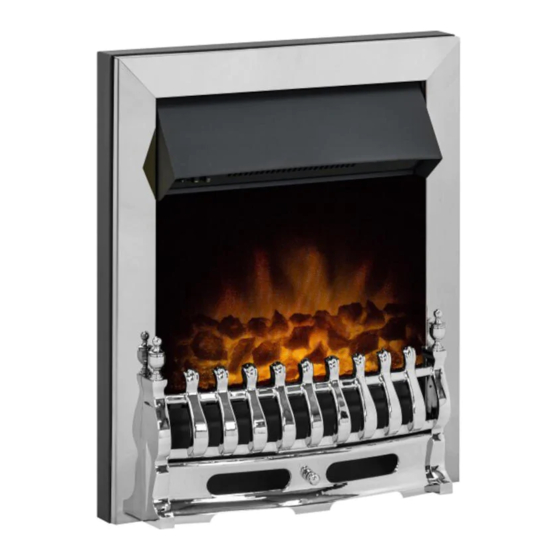
MULTIFLUE/INSET GAS FIRE
MODELS COVERED BY THESE INSTRUCTIONS
GRANGE MULTIFLUE
STROUD MULTIFLUE
SAWNAGE MULTIFLUE
WAREHAM MULTIFLUE
AVAILABLE WITH MANUAL, SLIDE CONTROL OR REMOTE CONTROL
MODEL SHOWN:WAREHAM MULTIFLUE
All instructions must be handed to the user for
1
safekeeping.
Revision A - 08/16
© 2016 Focal Point Fires plc.
GB IE
Advertisement
Chapters
Table of Contents

Related Manuals for Focal Point GRANGE MULTIFLUE


Summary of Contents for Focal Point GRANGE MULTIFLUE
- Page 1 Focal Point Fires plc. You are not permitted to copy or adapt any of the content without the prior written permission of Focal Point Fires plc.
-
Page 2: Table Of Contents
• Remote control models : These appliances features a battery-operated control system, and under normal usage will need a new battery approximately every twelve months. Refer to the appropriate section of these instructions for details of how to change the battery. © 2016 Focal Point Fires plc. -
Page 3: Appliance Data
DEPTH should be 168mm or greater for a flue used for solid fuel of oil burning appliances. Opening DEPTHS include any plaster or infill panels which form part of the installation. © 2016 Focal Point Fires plc. -
Page 4: Debris Collection Space
CLAY/CEMENT LINES OR BLOCK FLUE WHICH IS NEW, UNUSED, OR PREVIOUSLY ONLY USED WITH A GAS FIRE. X Dimension = 20mm UNLINED FLUE OR CHIMNEY WHICH HAS BEEN PREVIOUSLY USED FOR A SOLID FUEL OR OIL BURNING APPLIANCE X Dimension = 60mm © 2016 Focal Point Fires plc. -
Page 5: Ventilation
Self tapping screw pack; 4 No.8 x 5/16 Spigot restrictor Deflector baffle Set of manufacturers instructions Slide control position marking sticker (slide control models only) Slide control knob and M4 Nyloc nut (slide control models only) © 2016 Focal Point Fires plc. -
Page 6: Preparing The Appliance
8mm sup- ply pipe should be temporarily sealed to prevent the ingress of debris during fixing. PLEASE NOTE: Ensure fire can be removed for ease of servicing and not silconed © 2016 Focal Point Fires plc. -
Page 7: Gas Supply Routing
Now disconnect the inlet restrictor elbow from the inlet pipe. Connect the previously installed gas supply to inlet restrictor elbow, and re-fit the restrictor elbow to the inlet pipe of the appliance. Figure 10 © 2016 Focal Point Fires plc. -
Page 8: Gas Connection
Continue pressing down the knob while turning further to the left to activate the piezo spark, continue to hold the knob down for a further 10 seconds after the pilot has been lit. If the pilot does not light repeat the previous steps. © 2016 Focal Point Fires plc. -
Page 9: Operating The Fire (Slide Control)
MUST be of a type supplied for the purpose by the appliance manufacturer. If the fire is not spilling, then further guidance should be sought, using the Troubleshooting section as a guide. © 2016 Focal Point Fires plc. -
Page 10: Testing For Spillage
15. Check any purpose provided ventilation is un-obstructed. 16. Light the fire and test for spillage. 17. Check the operating pressure (see section 16.5) and safe operation of the appliance. For specific servicing instructions, see the relevant sections. © 2016 Focal Point Fires plc. -
Page 11: Cleaning The Ceramics
Ensure appliance is off and cool. The battery is located in the front of the ignition unit, on the right hand side of the burner (shown in figure 21). Unscrew the battery holder cap. Insert 1 x ‘AA’ (1.5 volt) battery. Replace cap. Figure 21 © 2016 Focal Point Fires plc. -
Page 12: Troubleshooting Guide
• Spillage occurring. Carry out Spillage test and rectify any problems. • Combustible materials used in incorrect positions. • Firebox grommet seal missing, rectify. • Other airborne contaminants such as dust, tobacco smoke, paint vapours. © 2016 Focal Point Fires plc. - Page 13 Any combustible side walls must be at least 500mm to the side of the radiant heat source. As with all heating appliances, any decorations, soft furnishings, and wall coverings (i.e. flock, blown vinyl and embossed paper) positioned too close to the appliance may discolour or scorch. © 2016 Focal Point Fires plc.
-
Page 14: Fire Guards
HIGH or LOW positions, press the control knob in, and return to the nine o’clock position and release.To turn the fire OFF, keep the knob pressed in, return to the off position and release. © 2016 Focal Point Fires plc. -
Page 15: Operating The Fire - Remote Control
Switch the appliance OFF, call in your installer to check any ventilation and carry out any remedial work required. DO NOT allow the appliance to be used until the installation is passed as safe. © 2016 Focal Point Fires plc. -
Page 16: Fuel Bed Layout - Ripped Coal Effect
Place the large brick panel against the rear of the firebox. Figure 13 Place the ceramic combustion matrix onto the burner and the ceramic side cheeks onto the matrix. © 2016 Focal Point Fires plc. -
Page 17: Fuel Bed Layout - Rounded Coal Effect
The rear two smaller coals are to be position in the centre and pushed back. The edges of the coals MUST NOT be allowed to enter the flame ports. © 2016 Focal Point Fires plc. -
Page 18: Servicing
Ensure appliance is off and cool. The battery is located in the front of the ignition unit, on the right hand side of the burner (shown in figure 22). Unscrew the battery holder cap. Insert 1 x ‘AA’ (1.5 volt) battery. Replace cap. Figure 22 © 2016 Focal Point Fires plc. -
Page 19: List Of Replacement Parts
Remote handset and receiver kit F730003/5 12.0 INSTALLATION DETAILS Name & contact details of installer : Supplied by : Installer GAS SAFE registration No : Model : Fire serial No. : Date installed : © 2016 Focal Point Fires plc. -
Page 20: Service History
Making a claim is easy. If you wish to make a claim under our guarantee and all the terms and conditions for your product have been met then please submit the following information for the attention of the 3G Service Department to the address below. Alternatively, you can email or fax. Focal Point Fires, 3G Service Department, Reid Street, Christchurch, Dorset, BH23 2BT. Email: 3g@focalpointfires.co.uk, Fax. 01202 588639.
Need help?
Do you have a question about the GRANGE MULTIFLUE and is the answer not in the manual?
Questions and answers