Advertisement
Quick Links
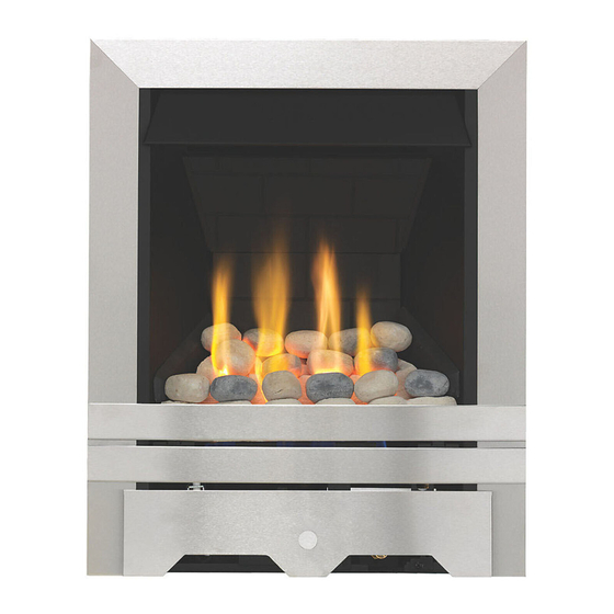
LULWORTH L L PG
FUEL E E FFECT G G AS F F IRE
INSTALLATION A A ND U U SER I I NSTRUCTIONS
All i i nstructions m m ust b b e h h anded t t o u u ser f f or s s afekeeping
Revision A - 08/06
Country(s) of destination - GB/IE
Focal Point Fires plc, Christchurch, Dorset BH23 2BT
Tel: 01202 499330
Fax: 01202 499326
www.focalpointfires.co.uk
e-mail: sales@focalpointfires.co.uk
Advertisement

Related Manuals for Focal Point LULWORTH LPG


Summary of Contents for Focal Point LULWORTH LPG
- Page 1 All i i nstructions m m ust b b e h h anded t t o u u ser f f or s s afekeeping Revision A - 08/06 Country(s) of destination - GB/IE Focal Point Fires plc, Christchurch, Dorset BH23 2BT Tel: 01202 499330 Fax: 01202 499326 www.focalpointfires.co.uk...
- Page 2 Lulworth LPG...
- Page 3 INST T ALLAT T ION I I NST T RUCT T IONS P P relim m in n ary N N otes B B efore I I n n stallation n This appliance is an Inset live fuel effect gas fire which provides radiant warmth utilising the latest type burner technology.
-
Page 4: Table Of Contents
Sec c tion Contents s Pag g e N N o. Sec c tion Pag g e N N o. Contents s Important Notes Cable Fixing Appliance Data Fitting the Burner Tray Installation Requirements Fuel Bed Layout Site Requirements 10.0 Fitting the Decorative Frame Debris Collection Space 11.0... -
Page 5: Appliance D D Ata
APPLIANCE D D ATA Gas Group G31 Propane CAT I3P Inlet Pressure 37 mbar Max Energy Input (gross) 6.2 kW Min Energy Input (gross) 3.5 kW Pilot Energy Input (gross) 166 W Setting Pressure 36.6 mbar (+/-0.75mbar) Main Injector Burner Stereo size 130 Gas Inlet Connection 8mm compression... - Page 6 SITE R R EQUIREMENTS The fireplace opening should be inspected and repairs made where necessary. Any chair brick or fireback may be left in situ, providing that the dimensional requirements for debris collection space and spigot clearances are met. See diagram below. The opening WIDTH and HEIGHT dimensions should be between 380mm and 450mm wide, and 540mm to 575mm high.
-
Page 7: Bs 5871 Part
DEBRIS C C OLLECTION S S PACE The mounting depth of this appliance is 108mm. In accordance with BS 5871 part 2, minimum debris collection volumes are required behind the installed appliance. These are shown in the table below and as dimension X on the fireplace diagram shown previously. CLAY/CEMENT L L INES O O R B B LOCK F F LUE W W HICH I I S N N EW, U U NUSED, O O R P P REVIOUSLY O O NLY U U SED W W ITH A A G G AS F F IRE. - Page 8 COMPONENT C C HECKLIST QUANTITY DESCRIPTION Firebox and burner tray assembly Decorative frame and firefront assembly Moulded ceramic fibre combustion matrix Individual ceramic pebbles Ceramic brick panel set Set of ceramic side cheeks Cable fixing kit; 2 cables, 2 tensioners, 2 cable clamps, 4 fixing eyes Sealing grommet Lengths of adhesive sealing strip Self tapping screw pack;...
-
Page 9: Cable Fixing
PREPARING THE OPENING ( ( continued) Cable f f ixing: For fixing the fire by the cable method, see relevant section. Fixing b b y s s crew: Mark and drill the fireframe or base, and relevant points in the opening or on the wall. Rawlplugs will be required. NOTE: Plastic rawlplugs are not suitable for this application. -
Page 10: Fitting The Burner Tray
FITTING THE BURNER TRAY Temporarily fit the burner tray and ensure a suitable gas route can be achieved. Place the burner tray into the firebox making sure that the rear lugs locate properly on to the ledge in the firebox. Fit the two securing screws through the tray legs to secure the assembly. Connect the gas supply and tighten the gas connections. -
Page 11: Spillage Monitoring System
12.0 FLUE SPILLAGE MONITORING SYSTEM This fire is fitted with a flue spillage safety device (ODS). If the fire shuts down during use for no apparent reason then several things may be suspected. If a door or window has been opened creating a draught, then pilot disturbance is the problem, and removal of the draught should resolve this. - Page 12 14.0 SERVICING - c c ontinued 8. Check the fireplace opening for rubble accumulation and remove. If debris is excessive, initiate remedial work on the flue. 9. Check the flue with smoke pellet for correct operation. 10. Refit convector box using new seals where necessary 11.
- Page 13 15.0 TROUBLESHOOTING G G UIDE Fire s s parks b b ut p p ilot d d oes n n ot l l ight No gas to fire, check isolators are open. Pipework blockage, clean out. Air not fully purged, repurge supply or wait longer. Spark earthing to metal work, reset gap correctly.
-
Page 14: Important N N Otes
USER INST T RUCT T IONS Sec c tion Contents s Pag g e N N o. Important Notes Firefront Clearances to Combustibles Ventilation Operating Instructions Fuel Bed Layout Flue Spillage Monitoring System Cleaning Servicing 10.0 Spares IMPORTANT N N OTES The installation of this fire MUST only be carried out by a competent person (such as a CORGI registered fitter) in accordance with the Gas Safety (Installation and Use) Regulations 1998, the relevant British Standards, Codes of Practice, the Building Regulations and the manufacturers’... -
Page 15: Fuel Bed Layout
FIREFRONT This fire is supplied with a particular style of firefront. Use of the firefront will ensure an adequate airflow under the fuelbed for the correct functioning of this appliance. Compliance with safety standards cannot be guaranteed if another style of front is used. CLEARANCES T T O C C OMBUSTIBLES A combustible shelf may be fixed to the wall above the fire, providing that it complies with the dimensions given below. - Page 16 FUEL BED LAYOUT - c c ontinued Place the front row of six pebbles on to the matrix. Ensure the pebbles are firmly against the side cheeks as shown in the photograph. If necessary, pull the peb- bles forward slightly to ensure their rear edges do not overhang the flame ports. The pebbles MUST NOT be allowed to enter the flame ports.
Need help?
Do you have a question about the LULWORTH LPG and is the answer not in the manual?
Questions and answers