Table of Contents
Advertisement
Quick Links
DWG2000-8G User Manual v1.0
Dinstar Technologies Co., Ltd.
Address: Floor 6, Guoxing Building, Changxing Road, Nanshan District, Shenzhen, China
Postal Code: 518052
Telephone: +86 755 2645 6664
Fax: +86 755 2645 6659
Emails: sales@dinstar.com, support@dinstar.com
Website: www.dinstar.com www.dinstar.cn
VoIPon www.voipon.co.uk sales@voipon.co.uk Tel: +44 (0)1245 808195 Fax: +44 (0)1245 808299
Advertisement
Table of Contents

Subscribe to Our Youtube Channel
Related Manuals for Dinstar DWG2000-8G


Summary of Contents for Dinstar DWG2000-8G
- Page 1 DWG2000-8G User Manual v1.0 Dinstar Technologies Co., Ltd. Address: Floor 6, Guoxing Building, Changxing Road, Nanshan District, Shenzhen, China Postal Code: 518052 Telephone: +86 755 2645 6664 Fax: +86 755 2645 6659 Emails: sales@dinstar.com, support@dinstar.com Website: www.dinstar.com www.dinstar.cn VoIPon www.voipon.co.uk sales@voipon.co.uk Tel: +44 (0)1245 808195 Fax: +44 (0)1245 808299...
- Page 2 DWG2000-8G User Manual Revision Records Document version Firmware version 9.50.41 Revised by Technical Support Department Date 2011/9/8 Changes The first version _______________________________________________________________________________ Dinstar Technologies Co., Ltd. VoIPon www.voipon.co.uk sales@voipon.co.uk Tel: +44 (0)1245 808195 Fax: +44 (0)1245 808299...
-
Page 3: Table Of Contents
DWG2000-8G User Manual Table of Contents 1. Equipment Introduction ......................... 4 1.1 Introduction ......................... 4 1.2 Scenario of Applications of Products .................. 4 1.3 Product Appearance ......................5 1.4 Functions and Features ......................6 1.4.1 Protocol Standard Supported ..................6 1.4.2 System Function ....................... - Page 4 DWG2000-8G User Manual 4.6.4 PIN Management ....................24 4.6.5 SMSC ........................24 4.6.6 SMS ........................25 4.6.7 USSD ........................25 4.6.8 Carrier ........................26 4.7 Routing Configuration ....................... 27 4.7.1 Routing Parameter ....................27 4.7.2 Tel->IP Routing ...................... 27 4.8 Manipulaton Configuration ....................30 4.8.1 IP->Tel Destination Numbers.................
-
Page 5: Equipment Introduction
This chapter mainly introduces functions and structures of DWG2000-8G. 1.1 Introduction DWG2000-8G is full functions VoIP gateway based on IP and GSM wireless network, which provides a flexible network configuration, powerful features, and good voice quality. It works for carrier grade, enterprise, SOHO, residential users for cost-effective solution. -
Page 6: Product Appearance
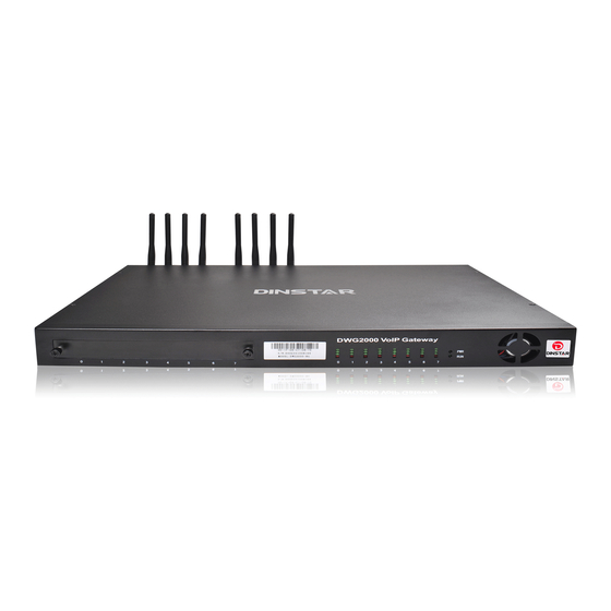
DWG2000-8G User Manual 1.3 Product Appearance The appearance of DWG2001 shows as follow Figure 1-3-1 Front view of DWG2000-8G Table 1-3-1 Description of Front view SIM Card Slot 8 SIM channel Red: Indicate that occupancy status of channels Indicator of Channels... -
Page 7: Functions And Features
DWG2000-8G User Manual Table 1-3-2 Description of Rear view Power Switch Turn on or turn off the device AC Power Input jack 8 SIM channel WAN interface LAN interface Indicate the run status of module POWER Indicate the Power status of module... -
Page 8: Industrial Standards Supported
DWG2000-8G User Manual 1.4.3 Industrial Standards Supported Stationary use environment: EN 300 019: Class 3.1 Storage environment: EN 300 019: Class 1.2 Transportation environment: EN 300 019: Class 2.3 Acoustic noise: EN 300 753 CE EMC directive 2004/108/EC ... -
Page 9: Equipment Installation
Wireless section, inserting SIM card directly, GSM channel should work properly. 2.2 Installation Procedure The outlook of DWG2000-8G looks like a 1U chassis; to install hardware the cable is needed. After unpacking the equipment, please do follow the procedure as following steps: 2.2.1 Install SIM Card... -
Page 10: Antenna Installation
DWG2000-8G User Manual Figure 2-2-1 Installing SIM card 2.2.2 Antenna Installation Take antenna connected in antenna interface of DWG which sign of "ANT" on Figure 2-2-2 Antenna Installation 2.2.3 Cable Connection of Equipment DWG2001 works in Route mode Figure 2-2-3 DWG2001 connection _______________________________________________________________________________ Dinstar Technologies Co., Ltd. -
Page 11: Network Configuration
Check the TT number of gateway (using just when the device interconnects *150*a# Set IP address(static/DHCP), a can be digit 1 or 2,*150*1# is static IP with other series of DINSTAR products) *152*a*b*c*d Configure IP address, a, b, c, d are the four fields of IP address. -
Page 12: Static Ip Configuration
DWG2000-8G User Manual *198# Clear record Setting Record. dial*199# start record(≤ 20s), then press # end the *199# *111# Restart device recording 3.4 Static IP Configuration This chapter introduces IP configuration of DWG2001 through calling IVR. Assuming the IP address of a DWG2001 device is 172.16.0.100, subnet mask is 255.255.0.0, IP of gateway is 172.16.0.1, configured as follows:... -
Page 13: Web Configuration
DWG2000-8G User Manual 4. WEB configuration This charpter describes web configuration of DWG2001. 4.1 Preparing WEB configuration includes the following components: network configuration, system information, mobile configuration and system configuration. 4.2 Access the System Through HTTP Enter IP address of DWG2001 in browser. The default IP of LAN port is 192.168.11.1. and the... -
Page 14: Web Configuration
DWG2000-8G User Manual 4.3 WEB Configuration DWG2001 WEB configuration interface consists of the navigation tree and the detail configuration interfaces. Figure 4-3-1 WEB introduce Go through navigation tree, user can check, view modify, and set the device configuration on the right of configuration interface. -
Page 15: Mobile Information
DWG2000-8G User Manual Figure 4-4-2 system information Table 4-4-1 Description of system information MAC Address Displays the current MAC of the gateway, for example: 00-1F-D6-1B-3D-02 Network Mode DWG2001 support two types network mode, which is bridge and route modes Network... -
Page 16: Sip Information
DWG2000-8G User Manual 4.4.3 SIP Information Figure 4-4-4 SIP information Displays registration status information with Softswitch platform or SIP Server Table 4-4-3 Description of SIP information Port He corresponding number of GSM channel, DWG2001 has only 1 port. SIP User ID... -
Page 17: Local Network
DWG2000-8G User Manual 4.5.1 Local Network Under the route mode, WAN port connects with ADSL modem, and LAN port connects with local network. It will be used as a small switch when working in brigde mode. In this situation, user just need to configure the WAN parameter and DNS. -
Page 18: Mac Clone
DWG2000-8G User Manual Table 4-5-1 Description of Local network Work Mode Two options of route mode and bridge mode, default is bridge mode The 5 options are “Auto Detect”,” 10Mbps/Half Link Speed & Duplex Duplex”,”10Mbps/Full Duplex”, “100Mbps/Half Duplex” and “100Mbps/Full Duplex”. Default is “Auto Detect”... -
Page 19: Dhcp Server
DWG2000-8G User Manual 4.5.3 DHCP Server Under “route mode”, DWG works as a router. Config DHCP serive to enable the DHCP service funcition of DWG, then DWG will works as a DHCP server. Figure 4-5-6 Configuration of DHCP service Table 4-5-2 Description of DHCP Server... -
Page 20: Forward Rules
DWG2000-8G User Manual 4.5.5 Forward Rules In some conditions, certain devices in LAN network need to provide channel communication with WAN network( e.g. certain computer in LAN network need to provide FTP service of channel 21 to WAN network). In this situation, Configuring forwarding rules to this device is necessary. -
Page 21: Qos Parameter
DWG2000-8G User Manual Table 4-5-4 Description of Static Route Dest IP Address Destination IP address the date packets will be sended Subnet Mask The Subnet Mask of Destination IP address Nexthop The Next Hop IP address if want to arrive the Destination IP addres 4.5.7 Qos Parameter... -
Page 22: Mobile Configuration
DWG2000-8G User Manual 4.6 Mobile Configuration 4.6.1 Basic Configuration Figure 4-6-1Basic Configuration Table 4-6-1 Description of Basic Configuration Dial Tone Gain It is the dial tone volume of call waiting, dial tone of mobile module when call out. Usually adopt the default configuration. - Page 23 DWG2000-8G User Manual 4.6.2Mobile Figure 4-6-2 Mobile Configuration Table 4-6-2 Description of Mobile Configuration SIM card user ID of the channel. That must be configured when “one access Mobile Number No.” funciton enable. Enable Call This function is to limit the max call duration of channel. The max call Duration duration is between 1 to 65535 minutes.
-
Page 24: Sim/Uim Card Lock
Detect Reverse This option for CMDA Reverse Polarity detection. Most CDMA operators Polarity don't offer polarity reverse . So VoIP to mobile, DWG2000-8G will connect soon. It doesn't wait mobile side answer. 4.6.3 SIM/UIM Card Lock Figure 4-6-3 Configuration of SIM/UIM Card Lock... -
Page 25: Pin Management
DWG2000-8G User Manual 4.6.4 PIN Management Figure 4-6-4 PIN Management Detailed description as below: Table 4-6-4 Description of PIN Management PIN is the password of SIM card personal identification. In the status of SIM card locked, PIN can be modified to prevent SIM card from being stolen. -
Page 26: Sms
DWG2000-8G User Manual 4.6.6 SMS Figure 4-6-6 SMS sending Configurations are as below: Table 4-6-5 Description of SMS sending Select Port Users can select a defined channel or random channel to send SMS. Input the recevier’s mobile phone No to send SMS. -
Page 27: Carrier
DWG2000-8G User Manual Table 4-6-6 Description of USSD Port Select the GSM channel to send USSD Display Display the result of sending USSD Input The area to input USSD code 4.6.8 Carrier Figure 4-6-8select Carrier This function is used to select carrier. -
Page 28: Routing Configuration
DWG2000-8G User Manual 4.7 Routing Configuration 4.7.1 Routing Parameter Figure 4-7-1 Routing Parameter Table 4-7-1Description of Routing Parameter Tel->IP Parameter Globle parameters, it will take effect while number manipulation configured Route calls after The parameters indicate that the gateway will select Tel->IP routes after... - Page 29 DWG2000-8G User Manual All the caller number must match the source prefix. It specifies the source prefix allow to send call out Any: include anonymous, 0xxxx, 1[2-9]xxxx etc. Source Prefix 0xxxx: consist of some digits such as 015,08,09 ...
- Page 30 DWG2000-8G User Manual Add a GSM to VoIP route. It indicates that the calls coming from Port Group 31<Unicom> will match the prefix ”x.”, ”x.” is a wildcard string which will match any prefix except ”anonymous” calls. Meanwhile sending the calls destination IP 13<eia> if called number match with destination prefix ”00”.
-
Page 31: Manipulaton Configuration
DWG2000-8G User Manual 4.8 Manipulaton Configuration 4.8.1 IP->Tel Destination Numbers Figure 4-8-1 IP->Tel destination numbers manipulation Table 4-8-1 Description of IP->Tel destination numbers manipulation It is an optional configuration item, and is used to add IP->Tel number IP->Tel destination change data. -
Page 32: Tel->Ip Source Numbers
DWG2000-8G User Manual Add an IP->Tel Manipulation, to change the called number from 2547888888 to 07888888 Figure 4-8-2 IP->Tel destination numbers manipulation modify It indecates that calls coming from IP Group will match the prefix ”any”, and the called nubmer whom match with the prefix ”2547”... - Page 33 DWG2000-8G User Manual All the caller number must match the source prefix. It specifies the source prefix allow to send call out Any: include anonymous, 0xxxx, 1[2-9]xxxx etc. Source Prefix 0xxxx: consist of some digits such as 015,08,09 ...
-
Page 34: Tel->Ip Destination Numbers
DWG2000-8G User Manual 4.8.3 Tel->IP Destination Numbers Figure 4-8-5 Tel->IP destination numbers manipulation Table 4-8-3 Description of Tel->IP destination numbers manipulation Tel->IP destination It is an optional configuration item, and is used to add IP->Tel number change data. numbers The IP->Tel Manipulation defined the rules of add, and deletion of called numbers, manipulation which are referenced by IP->Tel routing. - Page 35 DWG2000-8G User Manual Example Add an IP->Tel Manipulation, to change the called number from 2547888888 to 07888888 Figure 4-8-6 Tel->IP destination numbers manipulation It indecates that calls coming from IP Group will match the prefix ”any”, and the called nubmer whom match with the prefix ”2547”...
-
Page 36: Operation
DWG2000-8G User Manual 4.9 Operation 4.9.1 IP->Tel Operation Figure 4-9-1 IP->Tel Operation Table 4-9-1 Description of IP->Tel Operation It is an optional configuration item. Operation configuration essentially involves IP->Tel Operation allow, barring some IP and IP Group send calls to certain numbers. It includes: forbid call, call allowance, auto call, and password authentication. -
Page 37: Tel->Ip Operation
DWG2000-8G User Manual Example Index 31: barring the certain calling number from IP 14<elastix> Figure 4-9-2 IP->Tel Operation Modify It indicates that calling party from IP 14<elastix> matched prefix 2877, and also called party matched prefix 07 are not allowed call out. The calls match this rule will be rejected by gateway. - Page 38 DWG2000-8G User Manual Table 4-9-2 Description of Tel->IP Operation It is an optional configuration item. Operation configuration essentially involves Tel->IP Operation allow, barring some IP and IP Group send calls to certain numbers. It includes: forbid call, call allowance, auto call, and password authentication.
-
Page 39: Ip Trunk Configuration
DWG2000-8G User Manual 4.10 IP Trunk Configuration 4.10.1 IP Trunk Figure 4-10-1 IP Trunk Table 4-10-1 Description of IP Trunk Add remote IP of softswitch, SIP server which will send call traffics to gateway. IP Trunk Index It uniquely identifies a route. Its value is assigned globally, ranging from 0 to 31. -
Page 40: Ip Trunk Group
DWG2000-8G User Manual 4.10.2 IP Trunk Group Figure 4-10-3 IP Trunk Group Table 4-10-2 Description of IP Trunk Group This configuration is optional, and is used to add the IP that have the same IP Trunk Group attributes to an IP group. The IP group will referenced by IP->Tel routing and number manipulation. -
Page 41: System Configuration
DWG2000-8G User Manual 4.11 System Configuration 4.11.1 System Configuration Figure 4-11-1 System Configuration Table 4-11-1 Description of System Configuration Voice Prompt Language Configure the voice prompt of DWG., e.g. configure voice prompt of IP address success or failure. DWG supports English and Chinese. -
Page 42: Service Configuration
DWG2000-8G User Manual Provision Check Interval Default is 4 hours. Enable NTP NTP enable switch Primary NTP Server IP Can keep the default Secondary Provision NTP Can keep the default Server IP Time Zone The default is GMT +8:00, the user can adjusted accordingly according to their area 4.11.2 Service Configuration... - Page 43 LOCAL RTP PORT the IP network , in general, using the factory default values. When there Channel are multiple DINSTAR series voice products, and the network gateway or router’s NAT with loopholes, user can try changing this item Enable Silence Enable the "silence suppression"...
- Page 44 Caller ID for PSTN Incoming" setting is No, the caller User ID that sent to B will be C(except for anonymous outgoing ) DWG2001/DWG2000-4G/DWG2000-8G support RFC2833 and SIGNAL DTMF two ways. DTMF INTERVAL range is 50 ~ 800ms, DTMF VOLUME can use the default Configuration (Simple Traversal of UDP over NATs,NAT’s UDP simple cross) is a...
-
Page 45: Sip Configuration
DWG2000-8G User Manual 4.11.3 SIP Configuration Figure 4-11-3 SIP Configuration Used for Configuring VoIP channel, add SIP Registry Platform and local SIP Channel, and configure SIP protocol and other related information Configuration Used for configure SIP server address and Channel, the address can be IP... -
Page 46: Port Configuration
DWG2000-8G User Manual Used to keep communicate between equipment and the SIP server that make Keep alive the device is in the best available Registered. In general, using the factory Interval default values 4.11.4 Port Configuration Port Configuration is used to configure ports’ gain, Off-hook Auto-Dial, etc. -
Page 47: Digit Map
DWG2000-8G User Manual 4.11.5 Digit Map Figure 4-11-5 Digit map Digit Map Syntax: 1. Supported objects Digit: A digit from "0" to "9". Timer: The symbol "T" matching a timer expiry. DTMF: A digit, a timer, or one of the symbols "A", "B", "C", "D", "#", or "*". -
Page 48: Tools
4.12 Tools 4.12.1 Firmware Upload Equipment upgrades can through Dinstar’s softswitch platform, when the device disconnects with Dinstar’s softswitch platform or some special circumstances. The firmware is able to upload locally. Figure 4-12-1 Firmware upload Select the upgrade program under correct directory services, and then click upload will complete upgrade the firmware. -
Page 49: Data Backup
DWG2000-8G User Manual Figure 4-12-2 IVR Voice Prompt Upload NOTE: the customize voice files can be recorded using Windows recording programs, the sound format is 8000Hz, 16 bit sampling in mono, with WAV format, size of files can not exceed 190KB 4.12.3 Data Backup... -
Page 50: Login Password
DWG2000-8G User Manual Table 4-12-1 Description of Syslog Parameter Enable SysLog select yes to enable syslog client function Server Address Fill in the Syslog server IP Address here Syslog Level There are five level of syslog:NONE、DEBUG、NOTICE、WARNING、 ERROR, we urge you to select DEBUG. -
Page 51: Faq
DWG2000-8G User Manual 5. FAQ 5.1 Device have been connected to network physically, but the network cannot be connected or network communication is not normal 1) Make sure the network cable is ok or not , can through view the device WAN port or LAN port indicator light to determine the physical connection is working or not;... -
Page 52: Glossary
4) Make sure the LAN equipment is working, user can try to restart the gateway or router to solve the problem 5) Check whether there is more than one DINSTAR series products in LAN network: some gateways or routers, processing network packet is vulnerable (for example, to multiple network devices or the same protocol network communication, NAT allocated the same conversion communications Channel).
Need help?
Do you have a question about the DWG2000-8G and is the answer not in the manual?
Questions and answers