Table of Contents
Advertisement
Quick Links
DWG2000-1G User Manual v1.0
Dinstar Technologies Co., Ltd.
Address: Floor 9, Guoxing Building, Changxing Road, Nanshan District, Shenzhen, China
Postal Code: 518057
Telephone: +86 755 61919966
Fax: +86 755 2645 6659
Emails: sales@dinstar.com, support@dinstar.com
Website: www.dinstar.com,
www.dinstar.cn
Advertisement
Table of Contents

Related Manuals for Dinstar DWG2000-1G


Summary of Contents for Dinstar DWG2000-1G
- Page 1 DWG2000-1G User Manual v1.0 Dinstar Technologies Co., Ltd. Address: Floor 9, Guoxing Building, Changxing Road, Nanshan District, Shenzhen, China Postal Code: 518057 Telephone: +86 755 61919966 Fax: +86 755 2645 6659 Emails: sales@dinstar.com, support@dinstar.com Website: www.dinstar.com, www.dinstar.cn...
- Page 2 Revision Records Document Name DWG2000-1G User Manual v1.0 Document version V1.0 Firmware version 02361004 Shenzhen Dinstar Techonologies Co., Ltd Revised by Date 2014.4.15...
-
Page 3: Table Of Contents
1 Product Description ......................1 1.1 Overview ..............................1 1.2 Application Scenario ..........................1 1.3 Product Appearance ..........................2 1.3.1 Images of DWG2000-1G ........................2 1.3.2 Indicators and Related Explanation ...................... 3 1.4 Functions and Features ..........................3 1.4.1 Protocols Supported ..........................3 1.4.2 System Function ........................... - Page 4 5.3 USSD ..............................18 5.3.1 Configuration Procedures for USSD ....................18 5.4 GSM Audio Coding ..........................19 5.4.1 Introduction to GSM Audio Coding ....................19 5.4.2 Configuration Procedures for GSM Audio Coding................20 5.5 Abnormal Call Handle ........................... 21 5.5.1 Configuration Procedures for Abnormal Call Handle ................. 21 5.6 Enable Call Duration Limitation of Single Call &...
- Page 5 8.11 Auto Restart and Manually Restart ...................... 47 9 How to Connect with SIP Server ..................48 9.1 Configuration for connecting DWG2000-1G with Elastix through IP Trunking ........48 9.1.1 Configuration procedures on Elastix Sever ..................48 9.1.2 Configuration procedures on DWG2000-1G ..................50 9.2 Configuration Procedures for connecting DWG2000-1G with Elastix through SIP Registration with...
-
Page 7: Product Description
IP network. Thus, it can help reducing telephone costs for telecom operators, businesses, SOHO and residential users. DWG2000-1G not only provides seamless interconnectivity between the GSM/CDMA network and the IP network, but ensures smooth calling, good voice quality, flexible network configuration and other beneficial functions. 1.2 Application Scenario DWG2000-1G provides high-quality and cost-effective VoIP solution. -
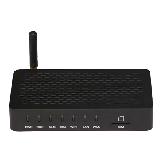
Page 8: Product Appearance
1.3 Product Appearance 1.3.1 Images of DWG2000-1G The above pictures are only for reference, and please take the real product as the standard. DWG2000-1G User Manual Copyright @ 2011-2015 Dinstar... -
Page 9: Indicators And Related Explanation
Explanation When the indicator is on green, it means DWG2000-1G is power on. When the indicator is on green with slow flash, it means DWG2000-1G is running normally; when the indicator is on green with fast flash, it means DWG2000-1G is reset. -
Page 10: Industrial Standards Supported
Power Supply:AC100~240V 50/60HZ DC12V/1A Temperature: 0~40 ℃ Operation , -20~80 ℃ storage Humidity: 5%~90% RH, Power Consumption: 12 W Dimensions: 126(W) x76 (D) x 25(H) mm Net weight: 0.2 kg DWG2000-1G User Manual Copyright @ 2011-2015 Dinstar... -
Page 11: Quick Installation
Connect the antenna to the DWG2000-1G device Connect the power wire to the DWG2000-1G device; Connect network cable (LAN cable and WAN cable) to the DWG2000-1G device; Insert the SIM card to the SIM slot. Power Adapter... -
Page 12: Web Management System
Web Management System 3.1 Introduction to Web Management System 3.1.1 Parts of Web Management Interface The web management system of the DWG2000-1G consists of the navigation tree and detailed configuration interfaces. 3.1.2 Login GUI of Web Management Interface Open a web browser and enter the IP address of the DWG2000-1G device (the default IP is 192.168.11.1). -
Page 13: Network Configuration
4.1 Working Mode of Network DWG2000-1G works in two modes: route mode and bridge mode. When it is under the route mode, the IP of WAN port must be different from the IP f LAN port. But when it is under the bridge mode, the IP of WAN and the IP of LAN are the same. -
Page 14: Network Connection Diagram
4.2.1 Network Connection Diagram Under the route mode, the default IP address of WAN port is a DHCP IP address, while the default IP address of the LAN port is a static IP address, namely 192.168.11.1. DWG2000-1G User Manual Copyright @ 2011-2015 Dinstar... -
Page 15: Configuration Procedures On Web Management System
The following procedures are based on the example where the IP address of WAN port is a static IP address while the IP address of LAN port is 192.168.11.1. Step 1. Open a web browser and enter the IP address of the DWG2000-1G device (the default IP is 192.168.11.1). Then a login GUI will be displayed. - Page 16 Use the following IP address, and fill in the following information. IP Address: the IP address of the DWG2000-1G device (it is 192.168.1.100 in this example). Subnet Mask: the subnet mask of the router connected the DWG2000-1G;...
-
Page 17: Network Configuration Under Bridge Mode
The following procedures are based on the example where both the IP address of WAN port and LAN port is 192.168.11.1. Step 1. Open a web browser and enter the IP address of the DWG2000-1G device (the default IP is 192.168.11.1). Then a login GUI of the Web Management System will be displayed. - Page 18 IP Address: the IP address of the DWG2000-1G, namely 192.168.11.1; Subnet Mask: the subnet mask of the router connected the DWG2000-1G; Default Gateway: the IP address of the router connected the DWG2000-1G. Step 6. Configure the IP address of DNS Server according to actual conditions.
-
Page 19: Mobile Configuration
SMS/USSD on the DWG. The protocol is carried over TCP and adopts a request/response method. To enable the SMS API function of the DWG2000-1G, the IP address, port, user ID and password of SMS Sever must be correctly configured, and the TCP Intercept function of the SMS Server must be enabled. - Page 20 Step 4. Configure the SMS Server according to actual conditions. Step 5. Log into the DWG2000-1G according to 3.1.2. Step 6. On the Web Management System GUI, click Mobile Configuration Basic Configuration. Step 7. Select the checkbox on the left of Yes for Remote API Enable.
- Page 21 Note: If the IP address of the DWG2000-1G is showed on the left, it means the connection between the gateway and the SMS Server is successful. Step 10. Send a message from the SMS Server to verify the SMS API function of the DWG2000-1G is effective.
-
Page 22: Send Sms & Receive Sms
Click Send Message, input message in the popup, and then click Send. 5.2 Send SMS & Receive SMS The DWG2000-1G can be used to send messages and receive massages. 5.2.1 Configuration Procedures for Sending SMS Step 1. In the navigation on the left, Click Mobile Configuration Send SMS. -
Page 23: Configuration Procedures For Receiving Sms
GSM 7bit Support English only Message The content of the message Step 3. Click Send. 5.2.2 Configuration Procedures for Receiving SMS Step 1. In the navigation on the left, Click Mobile Configuration Recv SMS. DWG2000-1G User Manual Copyright @ 2011-2015 Dinstar... -
Page 24: Ussd
Step 2. On the displayed interface, all the messages that the DWG2000-1G has received are shown. Step 3. If you want to delete a message, click the checkbox on the left of the message and then click Delete. 5.3 USSD USSD (Unstructured Supplementary Service Data): is a service which is provided by a telecom operator and allows GSM mobile phones to interact with the telecom operator's computers. -
Page 25: Gsm Audio Coding
Rate): the first digital speech coding speech standard used in the digital mobile phone system. The bit rate of the codec is 13 kbit/s, or 1.625 bits/audio sample (often padded out to 33 bytes/20 DWG2000-1G User Manual Copyright @ 2011-2015 Dinstar... -
Page 26: Configuration Procedures For Gsm Audio Coding
(200–3400 Hz) signals at variable bit rates ranging from 4.75 to 12.2 kbit/s with toll quality speech starting at 7.4 kbit/s. There are two modes for the AMR codec in the DWG2000-1G: AMR_FR:... -
Page 27: Abnormal Call Handle
Step 1. Log into the Web Management System GUI of the DWG2000-1G. Step 2. Enable CDR (the CDR on the DWG2000-1G is disabled by default). Click Statistics CDR Report, and select the checkbox on the left of Yes for CDR. - Page 28 Counts of Call Failed It is the counts of consecutive call failures. For example: If the value is 5, the gateway module will be blocked after the gateway detects 3 call failures consecutively. DWG2000-1G User Manual Copyright @ 2011-2015 Dinstar...
-
Page 29: Enable Call Duration Limitation Of Single Call & Enable Call Duration Limitation
5.6.1 Configuration Procedures for Enable Call Duration Limitation of Single Call 1. Log into the Web Management System GUI of the DWG2000-1G. 2. On the Web System Management GUI, click Mobile Configuration Mobile Configuration, and then click the checkbox on the left of Yes for Enable Call Duration Limitation of Single Call. -
Page 30: Configuration Procedures For Enable Call Duration Limitation
4. Click Save on the bottom of the interface. 5.6.2 Configuration Procedures for Enable Call Duration Limitation Step 1. Log into the Web Management System GUI of the DWG2000-1G. Step 2. On the Web Management System GUI, click Mobile Configuration Mobile Configuration, and then click the checkbox on the left of Yes for Enable Call Duration Limitation. - Page 31 The remaining call time of mobile number. For example, if maximum call duration is 60s and 40s has been consumed, the ‘SIM Remain Time’ is 20s. Step 4. Click Save on the bottom of the interface. DWG2000-1G User Manual Copyright @ 2011-2015 Dinstar...
-
Page 32: Clir & Detect Reverse Polarity
5.7.1 Configuration procedures for CLIR & Detect Reverse Polarity Step 1. Log into the Web Management System GUI of the DWG2000-1G. Step 2. On the Web System Management GUI, click Mobile Configuration Mobile Configuration, and then click the checkbox on the left of Yes for CLIR & Detect Reverse Polarity. -
Page 33: Configuration Procedures For Bcch
5.8.1 Configuration Procedures for BCCH Step 1. Log into the Web Management System of the DWG2000-1G. Step 2. On the Web Management System, click Mobile Configuration BCCH. Step 3. Drag the scroll bar on the bottom of the interface, and you will see a button. -
Page 34: Carrier
Step 9. Click the Save button on the interface. 5.9 Carrier On the Mobile Configuration Carrier interface, if Automatic is selected, the DWG2000-1G device will automatically identify the carrier which the inserted SIM card belongs to. If Manual is selected, you need to choose a carrier in the drop-down box. -
Page 35: Call Forwarding
Calls will not be forwarded. Call Number The number where calls will be forwarded. 5.11 Call Waiting On the Mobile Configuration Call Waiting interface, the call waiting function can be disabled or enabled. DWG2000-1G User Manual Copyright @ 2011-2015 Dinstar... -
Page 36: Call Control
6.2 IP Tel Calls and Tel IP Calls As the DWG2000-1G device provides interconnectivity between the GSM network and the IP network, we define calls from the IP network to the GSM network as outgoing calls (IP Tel calls), and define calls from GSM network to the IP as incoming calls (Tel IP calls). -
Page 37: Configuration Of Ip Trunk Group
The IP address of the device (for example: DAG) connected to the DWG2000-1G. Port The port of the device (for example: DAG), through which the DWG2000-1G is connected to the device. Description You can enter any description you want. -
Page 38: Routing Configuration
6.4 Routing Configuration Step 1. In the navigation tree on the left, click Routing Configuration Tel -> IP Routing, and the following interface will be displayed. Step 2. Click Add to configure routing. DWG2000-1G User Manual Copyright @ 2011-2015 Dinstar... -
Page 39: Operation
The Operation function is used to control outgoing calls and incoming calls. It can determine whether a call is allowed or forbidden. 6.5.1 Configuration Procedures for IP -> Tel Operation Step 1. In the navigation, click Operation IP->Tel Operation, and the following interface will be displayed. DWG2000-1G User Manual Copyright @ 2011-2015 Dinstar... - Page 40 2009966, Allow Call and Auto Call are selected, the outgoing call of 2009966 will be dialed by the DWG2000-1G automatically. Description Enter any description that you want. Note: If Auto Call is selected, IP -> Tel call will be dialed by the DWG2000-1G automatically. Step 3. Click OK. DWG2000-1G User Manual...
-
Page 41: Configuration Procedures For Tel -> Ip Operation
The prefix of the destination number. When a destination number includes this Prefix prefix, the operation will be executed. Operation Operation includes Forbid Call, Callback, Play IVR Only, Allow Call, Auto Call and Password Authentication. DWG2000-1G User Manual Copyright @ 2011-2015 Dinstar... -
Page 42: Number Manipulation
Step 1. In the navigation tree of Web Management System, click Manipulation Configuration IP –> Tel Destination Numbers, and the following interface will be displayed. Step 2. Click Add, and the following interface will be displayed. DWG2000-1G User Manual Copyright @ 2011-2015 Dinstar... - Page 43 From Right , Prefix/Suffix to Add and Number of Digits to Leave from Right) are the rules to change numbers. Step 3. Click OK Step 4. If you need to delete or modify the configuration, click the on the left, and then click Delete or Modify. DWG2000-1G User Manual Copyright @ 2011-2015 Dinstar...
-
Page 44: Statistics
On the Statistic RTP interface, the data packages related to RTP (Real-time Transport Protocol) are displayed. The packages can be refreshed automatically or manually. If data are shown, it means a call is ongoing. DWG2000-1G User Manual Copyright @ 2011-2015 Dinstar... -
Page 45: Sip Call History
Statistic IP to GSM Call History interface, history of IP GSM calls is displayed. 7.6 CDR Report Statistic CDR Report interface, details of all calls through the port of DWG2000-1G are On the displayed. The CDR function can be enabled on this interface. -
Page 46: Lock Bcch Report
On the Statistics Lock BCCH Report interface, history of the changes of BCCH frequencies is shown. 7.8 Current Call Status On the Statistics Current Call Status, status and detail of the current call are shown. DWG2000-1G User Manual Copyright @ 2011-2015 Dinstar... -
Page 47: Tools
Tools 8.1 Navigation Subtree of Tools 8.2 Firmware Upload On the Tools Firmware Upload, you can upload a firmware to upgrade the DWG2000-1G. But you need to restart the DWG2000-1G device for the change to take effect. 8.3 Provision On the Tools ... -
Page 48: Configuration On Ftp Server
“36” (36 is the product ID of DWG). Step 2. Ask the technical support of Shenzhen Dinstar Technology Co.,Ltd to provide the following compression package, which contains two files (the “package” file and the “wgpkgmipsel.ldf” file). -
Page 49: Configuration On Dwg2000-1G
Step 6. Put the following files in the “36” folder. (Except the “default” file, other files are provided by Dinstar.) 8.3.2 Configuration on DWG2000-1G Step 1. Log into the Web Management System of the DWG2000-1G Step 2. On the navigation tree on the left, click Tools Provision, and the following interface will be displayed. -
Page 50: Filelog Download
Proxy Domain, Proxy Port, Proxy Account and Proxy Password are optional to be configured. Step 3. Click the Save button. 8.4 Filelog Download The filelog which indicates the details of the operations carried out on the DWG2000-1G device can be downloaded on the Tools Filelog Download. 8.5 Management Parameter On the Tools ... -
Page 51: Config Backup & Config Restore
On the Tools IVR Voice Prompt Upload interface, you can upload a IVR prompt or set a default IVR prompt for PSTN incoming calls. 8.8 Network Diagnosis 8.8.1 Ping Test On the Tools Ping Test interface, you can use Ping to check whether the network is working or not. DWG2000-1G User Manual Copyright @ 2011-2015 Dinstar... -
Page 52: Tracert Test
On the Tools Network Capture interface, you can capture data packages of the available network ports. 8.9 Username & Password If you want to change the username or password of the DWG2000-1G device, click Tools Username & Password. You are required to enter old username and password before inputting new username and password. -
Page 53: Factory Reset
8.10 Factory Reset On the Tools Factory Reset interface, click Apply, and the DWG2000-1G device will be reset The factory settings. 8.11 Auto Restart and Manually Restart On the Tools Auto Restart interface, you can choose enable or disable Auto Restore. -
Page 54: How To Connect With Sip Server
How to Connect with SIP Server This chapter is aimed to describe the configuration procedures for connecting the DWG2000-1G with SIP server. Here we take the Elastix Server for example. 9.1 Configuration for connecting DWG2000-1G with Elastix through IP Trunking 9.1.1 Configuration procedures on Elastix Sever... - Page 55 DWG2000-1G) Secret (the authentication password for connecting with the Elastic Server) Step 4. Click Outbound Routes in the navigation tree to configure outbound route on the Add Outbound Routes interface, and fill in the following information.
-
Page 56: Configuration Procedures On Dwg2000-1G
Step 8. Apply configuration changes. 9.1.2 Configuration procedures on DWG2000-1G Step 1. Log into the Web Management System of DWG2000-1G. Step 2. On the navigation tree on the right, click System Configuration SIP Parameter, and the following interface will be displayed. - Page 57 Authenticate Password: the secret set in Step 3 of the configuration on Elastix Server. To VOIP Hotline: the inbound number that is dialed automatically by the DWG2000-1G when ‘Auto Call’ is selected in the Operation Tel-> IP Operation interface (make reference to 6.5.2) To PSTN Hotline: the outbound number that is dialed automatically by the DWG2000-1G when ‘Auto Call’...
- Page 58 Step 7. On the navigation tree, click Operation IP->Tel Operation, click Add on the displayed on the left of ‘Auto Call’ to enable ‘to PSTN Holine’. interface, and then click DWG2000-1G User Manual Copyright @ 2011-2015 Dinstar...
-
Page 59: Trunking
Step 2. Click PBX on the menu at the top of the interface top, and then click Trunks in navigation tree on the left. Step 3. Click Add SIP Trunk to create a SIP Trunk to DWG2000-1G. Fill in the following information Outgoing settings ... - Page 60 Secret (the authentication password for connecting with the Elastic Server) Step 4. Click Outbound Routes in the navigation tree to configure outbound route, and fill in the following information. DWG2000-1G User Manual Copyright @ 2011-2015 Dinstar...
- Page 61 DID number (the number for access to this route, ‘123’ in this example) Destination (the extension number that the route will reach, ‘101’ in this example) Step 7. Click Submit to save the changes. DWG2000-1G User Manual Copyright @ 2011-2015 Dinstar...
-
Page 62: Configuration Procedures On Dwg2000-1G
Step 8. Apply configuration changes. 9.2.2 Configuration Procedures on DWG2000-1G Step 1. Log into the Web Management System of DWG2000-1G. Step 2. On the navigation tree on the right, click System Configuration SIP Parameter, and the following interface will be displayed. - Page 63 Authenticate Password: the secret set in Step 3 of the configuration on Elastix Server. To VOIP Hotline: the inbound number that is dialed automatically by the DWG2000-1G when ‘Auto Call’ is selected in the Operation Tel-> IP Operation interface (make reference to 6.5.2) To PSTN Hotline: the outbound number that is dialed automatically by the DWG2000-1G when ‘Auto Call’...
- Page 64 Step 8. Click OK at the bottom of the interface. ---End DWG2000-1G User Manual Copyright @ 2011-2015 Dinstar...
Need help?
Do you have a question about the DWG2000-1G and is the answer not in the manual?
Questions and answers