Table of Contents
Advertisement
Quick Links
Advertisement
Table of Contents

Related Manuals for Crestron ST-VS


Summary of Contents for Crestron ST-VS
- Page 1 Crestron ST-VS Video Sensor Module Operations Guide...
- Page 2 This document was prepared and written by the Technical Documentation department at: Crestron Electronics, Inc. 15 Volvo Drive Rockleigh, NJ 07647 1-888-CRESTRON All brand names, product names and trademarks are the property of their respective owners. © 2003 Crestron Electronics, Inc.
-
Page 3: Table Of Contents
Crestron ST-VS Contents Video Sensor Module: ST-VS Introduction ... 1 Features and Functions... 1 Specifications ... 1 Physical Description... 2 Industry Compliance ... 5 Setup ... 6 Identity Code ... 6 Hookup ... 6 Programming Software... 7 Earliest Version Software Requirements for the PC ... 8 Programming with SIMPL Windows... -
Page 5: Video Sensor Module: St-Vs
Default Net ID Specifications continued on next page. Operations Guide – DOC. 5767A ® video sensor, ST-VS, is used to detect the presence of a video signal • The ST-VS is used to detect the presence of a baseband video signal •... -
Page 6: Specification
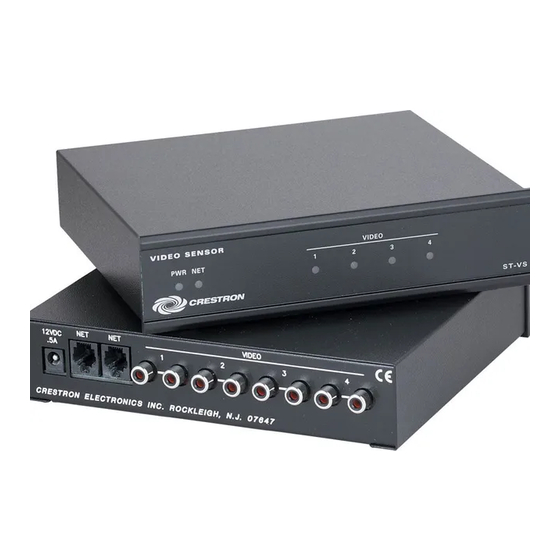
FTP site). Physical Description The ST-VS is housed in a black enclosure with labels on the front and rear panels. On the front of the unit there are six LEDs for indicating the unit’s current status. All connections are made to the back of the unit. Refer to the physical view shown after this paragraph. - Page 7 (15.58 cm) 6.32 in (16.06 cm) VIDEO SENSOR 1.78 in (4.52 cm) Video Sensor Module CRESTRON ELECTRONICS INC. ROCKLEIGH, N.J. 07647 6.94 in (17.63 cm) 7.07 in (17.95 cm) VIDEO PWR NET CRESTRON Video Sensor Module: ST-VS • 3 ST-VS...
- Page 8 Video Sensor Module Ports A number of ports are provided on the back of the ST-VS. Each has a silk-screened label. Refer to the illustration and descriptions below. ST-VS Ports 12 VDC .5A NOTE: If the ST-VS is part of the Cresnet system, use of this port is optional.
-
Page 9: Industry Compliance
(two per video signal) connect to the (up to) four independent sources that require sensing. Indicators There are six LED indicators located on the front panel of the ST-VS. Each has a silk-screened label. Refer to the illustration and descriptions below. ST-VS Indicators... -
Page 10: Setup
Refer to “Setting the Net ID in Device Settings” on page 10 for details of the SIMPL Windows procedure. The Net ID of the ST-VS has been factory set to 3C, The Net IDs of multiple ST- VSs in the same system must be unique. Net IDs are changed from a personal Refer to the note on page 11 for a computer (PC) via the Crestron Viewport. -
Page 11: Programming Software
NOTE: When installing network wiring, refer to the latest revision of the wiring diagram(s) appropriate for your specific system configuration, available from the Downloads | Product Manuals | Wiring Diagrams section of the Crestron website (www.crestron.com). NOTE: Refer to the latest revision of the Crestron Network Modular Cable Requirements (Doc. -
Page 12: Earliest Version Software Requirements For The Pc
Video Sensor Module Earliest Version Software Requirements for the PC NOTE: Crestron recommends that you use the latest software to take advantage of the most recently released features. The latest software is available from the Downloads | Software Updates section of the Crestron website (www.crestron.com). - Page 13 Net ID of 3C as shown in the following illustration. NOTE: The first ST-VS in a system is preset with a Net ID of 3C when its symbol is dragged into the upper pane of System Views. Additional ST-VS units are assigned different Net ID numbers as they are added.
- Page 14 Setting the Net ID in Device Settings Double-click the ST-VS icon to open the “Device Settings” window. This window displays the ST-VS device information. If necessary, select the Net ID tab to change the Net ID as shown in the following figure.
-
Page 15: Uploading
The device extenders are available with X-Series and 2-Series control systems; they are not available with the ST-CP or CN-Series control systems. To add a device extender, right-click the ST-VS in Program View, point to Insert Device Extender and select the desired device extender. To program a device extender, expand the ST-VS in Program View and drag the device extender to Detail View. - Page 16 The procedure in this section provides details for RS-232 communication between the PC and the control system. If TCP/IP communication is preferred, consult the latest version of the Crestron e-Control Reference Guide (Doc. 6052) or the respective Operations Guide for the control system. These documents are available from the Downloads | Product Manuals section of the Crestron website (www.crestron.com).
-
Page 17: Uploading A Simpl Windows Program
Guide for the control system. 1. Start SIMPL Windows. 2. Select File | Open to view the “Open” window, navigate to the SIMPL Window file (.smw), and click Open. 3. Select Project | Transfer Program. Video Sensor Module Video Sensor Module: ST-VS • 13... - Page 18 NOTE: Refer to the respective Operations Guide for control system details about the other fields in the “Send Program” window. 14 • Video Sensor Module: ST-VS 1. Verify that the procedure for “Communication Settings” that begins on page 11 has been performed.
-
Page 19: Problem Solving
Crestron ST-VS Problem Solving Troubleshooting The following table provides corrective action for possible trouble situations. If further assistance is required, please contact a Crestron customer service representative. ST-VS Troubleshooting Unexpected response from control system. Operations Guide – DOC. 5767A TROUBLE... -
Page 20: Further Inquiries
Crestron award winning customer service team by calling: You can also log onto the online help section of the Crestron website (www.crestron.com) to ask questions about Crestron products. First-time users will need to establish a user account to fully benefit from all available features. -
Page 21: Return And Warranty Policies
(property or economic damages inclusive) arising from the sale or use of this equipment. CRESTRON is not liable for any claim made by a third party or made by the purchaser for a third party. - Page 22 Video Sensor Module Crestron ST-VS This page intentionally left blank. 18 • Video Sensor Module: ST-VS Operations Guide – DOC. 5767A...
- Page 23 Crestron ST-VS Video Sensor Module This page intentionally left blank. Video Sensor Module: ST-VS • 19 Operations Guide – DOC. 5767A...
- Page 24 Crestron Electronics, Inc. Operations Guide – DOC. 5767A 15 Volvo Drive Rockleigh, NJ 07647 12.03 Tel: 888.CRESTRON Fax: 201.767.7576 Specifications subject to www.crestron.com change without notice.
Need help?
Do you have a question about the ST-VS and is the answer not in the manual?
Questions and answers