Advertisement
Quick Links
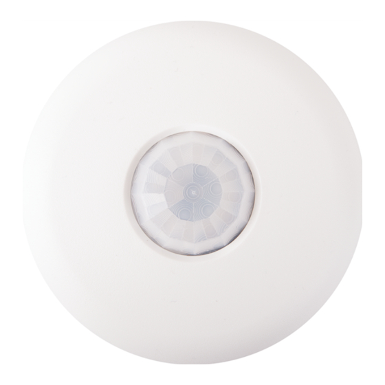
ZUMMESH-PIR-OCCUPANCY-BATT/ZUMMESH-PIR-VACANCY-BATT
Zūm™ Occupancy Sensor and Vacancy Sensor
Installation Guide
Description
The Crestron® Zūm™ occupancy and vacancy sensors detect when a person enters and
exits a space. They communicate wirelessly with Zūm™ wireless devices to turn the
lights on and off based on room occupancy and vacancy.
Featuring passive infrared (PIR) technology, the ZUMMESH-PIR-OCCUPANCY-BATT
(occupancy sensor) and ZUMMESH-PIR-OCCUPANCY-BATT (vacancy sensor) reliably
detect when a person enters and exits the space.
Install up to 8 occupancy or vacancy sensors to ensure coverage in a large room.
NOTE: Do not mix occupancy and vacancy sensors in the same room.
NOTE: When using the ZUMMESH-AVBRIDGE with an AM-200 or AM-300:
• To install, refer to the "Installation," "Calibration and Testing," and
"Mounting and Masking Locations" sections that follow.
• To configure, refer to the AM-200/AM-300 Product Manual (Doc. 8254) at
www.crestron.com/manuals
for wireless connections, setup, and operation.
Zūm Overview
A Zūm space consists of one space, such as a board room or conference room, that
is equipped with Zūm mesh devices. The Zūm mesh devices (i.e., dimmers, switches,
keypads, and sensors) in the space provide control and communicate directly with
each other without the need for a centralized gateway or processor.
To expand the functionality of the Zūm space, a ZUMMESH-NETBRIDGE (not
included) can be added which provides centralized control and monitoring from a
Crestron control system (not included).
NOTE: The ZUMMESH-NETBRIDGE requires a compatible J-box device (not
included) to provide power.
Select the Mounting Location
Use the following diagrams to determine the mounting location for the occupancy or
vacancy sensor. Ensure a vibration-free mounting surface.
Side View - 8-12 ft
Sensor Coverage Areas - Side View 8-12 ft (~2.5-3.5 m)
(~2.5-3.5 m)
0 ft
(0 m)
8 ft
(~2.5 m)
10 ft
(~3 m)
12 ft
(~3.5 m)
20 ft
15 ft
10 ft
5 ft
0 ft
5 ft
10 ft
15 ft
(~6 m)
(~5 m)
(~3 m)
(~2 m)
(0 m)
(~2 m)
(~3 m)
(~5 m)
Sensor Coverage Areas - Top View (8 ft (~2.5 m)
Top View - 8 ft (~2.5 m)
15 ft
(~5 m)
C L
10 ft
(~3 m)
5 ft
(~2 m)
0 ft
(0 m)
5 ft
(~2 m)
10 ft
(~3 m)
15 ft
(~5 m)
NOTE:
• The occupancy and vacancy sensors must have a clear view of the entire
room. The device should not be blocked by furniture or fixtures.
• Avoid false triggering by mounting it away from air vents, fans, windows,
and other devices that create air movement in the room.
Install the Sensor
To complete the installation, the occupancy and vacancy sensors ship with (2) Plastic
wall anchors, (2) Phillips head screws, and (1) Ultralife 9 volt lithium battery. A Phillips
tip screwdriver and a pencil are required for installation (not included).
If desired, the sensor may be painted to match the ceiling color. However, do not paint
over the dome as this significantly hinders sensing capabilities.
NOTE: Install and use this product in accordance with appropriate electrical codes
and regulations.
Mount the sensor to the ceiling.
1. Mark the location for the two plastic wall anchors. The marks should be 3 in
(76 mm) apart.
2. Install the plastic wall anchors.
NOTE: For surfaces other than drywall and drop-ceiling tiles, pre-drill the
mounting location for the plastic wall anchors.
3. Twist the sensor cover counterclockwise to separate the cover from the base.
Hold the sensor base in the palm of your
hand and twist the cover counterclockwise
to separate the base from the sensor cover.
4. Secure the base to the plastic wall anchors using the provided Phillips head
screws.
5. Connect the battery to the two terminals in the sensor and secure the battery to
the base.
20 ft
(~6 m)
6. Place the cover on the base and then twist the cover clockwise to secure it to the
base. The assembly clicks when secured.
C L
Rotate to secure
the cover.
Operate the Occupancy or Vacancy Sensor
Occupancy and vacancy sensors toggle the lights and plug controllers in the room
based on the room status.
Up to 8 Occupancy or Vacancy sensors can be installed in the same space. When
multiple sensors are installed, the space is considered occupied when any sensor
detects motion and the space is considered vacant after all sensors detect vacancy.
NOTE: After an occupancy or vacancy sensor stops detecting motion, a timeout
period occurs and then it turns off the lights (recalls scene 16 from the load
controller). Refer to the "Timeout Settings" section to set the timeout.
Occupancy Sensor Control
The occupancy sensor controls the lights and the plug controller based on occupancy or
vacancy. Refer to the chart below for details.
Occupied
Vacant
Lights
Turn On (scene 1)
Turn Off
Plug Controller
Turn On
Turn Off
Vacancy Sensor Control
The vacancy sensor controls the lights and the plug controller based on occupancy or
vacancy. If the vacancy sensor detects motion within 30 seconds of turning off the
lights, the vacancy sensor switches the lights back on.
Refer to the chart below for details.
Occupied
Vacant
Lights
No Action
Turn Off
Plug Controller
Turn On
Turn Off
NOTE:
• Sensors may not work as expected if occupancy is detected, the lights turn
on, and then the user manually turns off the lights from a local switch and
decides to re-enter the room before the timeout has completed. In this
situation, the lights will not turn on automatically. The sensor is reliant on
a full completion of cycles (vacancy, then occupancy, then vacancy) to work
correctly.
• Rooms can be programmed to be occupied while the lights are off by utilizing
scenes or sensor-disabling buttons.
Calibrate and Test the Sensor
Adjust the settings that are available under the sensor cover and then test the
operation.
Timeout Settings
The time that the sensor takes to declare the room vacant after motion is no longer
detected is determined by the timeout setting. The timeout knob inside the sensor can
be set between 30 seconds and 30 minutes.
If no motion is detected during the timeout period, the lights turn off. If motion is
detected during the timeout period, the sensor waits until it no longer detects motion
and then begins a new timeout period.
A timeout of 15 minutes would be typical for a conference room application.
Sensitivity Settings
Set the sensitivity of the sensor to high for normal use. If false triggers occur, turn
down the sensitivity until false triggers no longer occur.
Test Button
Press the TEST button to verify that the sensor is connected to the system. The lights in
the space toggle to indicate that the device is connected.
Mask the Sensor
To prevent unwanted motion from triggering the lights, install a mask in the sensor to
conceal the lens and to block the view of certain areas in the space. Use the
PIR 1/2 mask to block half of the detection range or the perforated PIR 360-degree
(12-section, 30-degree per section) mask to provide custom masking.
NOTE: The half mask comes preinstalled. If the perforated mask is to be used, it
should be installed in the same manner as the half mask.
Refer to the following illustrations for typical masking applications. The first
illustration shows a PIR 360-degree mask, the second shows a PIR 1/2 mask.
Test Mode
Test mode allows the installation location of the occupancy or vacancy sensor to be
verified. Test mode exits automatically after 2 minutes.
To enter Test mode, press and hold the TEST button until the LED lights. While in test
mode, the green LED flashes slowly.
Press and hold 2 sec.
Walk around the room and in front of windows and open doorways to verify
operation. The red LED lights when motion is detected.
Advertisement

Related Manuals for Crestron Zum ZUMMESH-PIR-OCCUPANCY-BATT


Summary of Contents for Crestron Zum ZUMMESH-PIR-OCCUPANCY-BATT
- Page 1 Operate the Occupancy or Vacancy Sensor Mask the Sensor The Crestron® Zūm™ occupancy and vacancy sensors detect when a person enters and To complete the installation, the occupancy and vacancy sensors ship with (2) Plastic Occupancy and vacancy sensors toggle the lights and plug controllers in the room To prevent unwanted motion from triggering the lights, install a mask in the sensor to exits a space.
- Page 2 15 of the FCC Rules. These limits are designed to provide reasonable Crestron Electronics, Inc. in the United States and/or other countries. UL and the UL logo are This Class B digital apparatus complies with Canadian ICES-003.
Need help?
Do you have a question about the Zum ZUMMESH-PIR-OCCUPANCY-BATT and is the answer not in the manual?
Questions and answers