Table of Contents
Advertisement
Quick Links
Advertisement
Table of Contents

Related Manuals for Crestron ST-CS


Summary of Contents for Crestron ST-CS
- Page 1 Crestron ST-CS Current Sensor Module Operations Guide...
- Page 2 This document was prepared and written by the Technical Documentation department at: Crestron Electronics, Inc. 15 Volvo Drive Rockleigh, NJ 07647 1-888-CRESTRON All brand names, product names and trademarks are the property of their respective owners. © 2004 Crestron Electronics, Inc.
-
Page 3: Table Of Contents
Crestron ST-CS Contents Current Sensor Module: ST-CS Introduction ... 1 Features and Functions... 1 Specifications ... 2 Physical Description... 3 Setup ... 7 Identity Code ... 7 Hardware Hookup ... 8 Threshold Adjustment ... 10 Programming Software... 10 Earliest Version Software Requirements for the PC ... 11 Programming with SIMPL Windows... -
Page 5: Current Sensor Module: St-Cs
220 VAC devices. For purposes of this Operations Guide, the term ST-CS is used for either configuration, except where noted. The ST-CS measures the average current of each half cycle of an AC load. The current sensing circuitry is highly sensitive with a wide range of adjustment. The high sensitivity makes the ST-CS ideally suited for use with low power units as VCRs, TV tuners, and satellite receivers. -
Page 6: Specifications
Current Sensor Module Specifications The following table provides a summary of specifications for the ST-CS module. ST-CS Specifications Power Requirements Default Net ID Control System Update Files Ports/Connectors Rack Space Environmental Temperature Environmental Humidity Dimensions & Weight NOTE: Crestron software and any files on the website are for Authorized Crestron dealers and Crestron Authorized Independent Programmers (CAIP) only. -
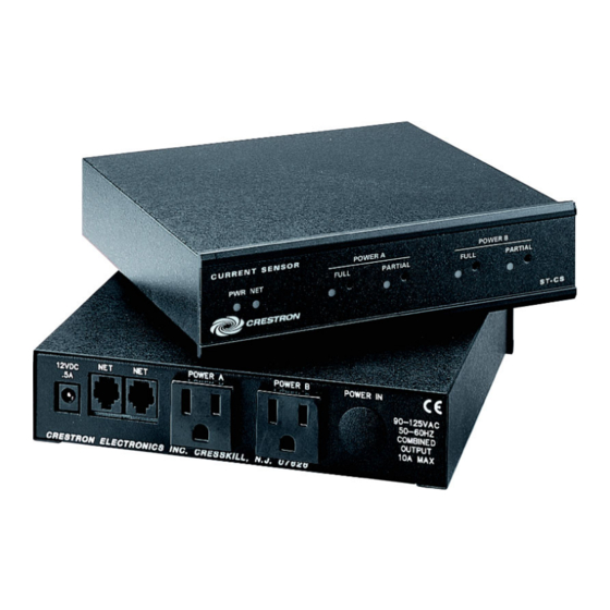
Page 7: Physical Description
Crestron ST-CS Physical Description The ST-CS is housed in a black enclosure with labels on the front and rear panels. On the front of the unit there are six LEDs for indicating current status, power, and Cresnet activity. The front panel provides four potentiometers (POTs) for adjusting the current sensing sensitivity. - Page 8 Current Sensor Module ST-CS Physical Views (120 VAC Version) 1.50 in (3.81 cm) 6.13 in (15.58 cm) 6.32 in (16.06 cm) 1.78 in (4.53 cm) 4 • Current Sensor Module: ST-CS POWER A 12VDC CRESTRON ELECTRONICS INC. CRESSKILL N.J. 07626 6.94 in...
- Page 9 Crestron ST-CS STI-CS Physical Views (220 VAC Version) Ports A number of ports and plugs are provided on the back of the ST-CS. Each has a silk- screened label. Refer to the following illustrations and descriptions. ST-CS Ports and Plugs Operations Guide –...
- Page 10 500 mA power pack (1000 mA power pack for STI-CS). The supplied power pack is optional when the ST-CS receives network power. These two 6-pin, RJ-12 modular jacks are used to connect the ST-CS module to a control system. When the module is part of the Cresnet supplied via NET if within system power and cable length limits;...
-
Page 11: Setup
Refer to “Setting the Net ID in Device Settings” on page 12 for details of the SIMPL Windows procedure. The Net ID of the ST-CS has been factory set to 18, The Net IDs of multiple ST-CSs Refer to the note on page 14 for a definition of Viewport. -
Page 12: Hardware Hookup
(i.e., display device) to the ST-CS POWER A connector and adjust the POTS. If necessary, repeat the steps and attach a second device to POWER B. - Page 13 POWER IN 90-125VAC 50-60HZ COMBINED OUTPUT 10A MAX PLUG INTO AC OUTLET DEVICE REQUIRING CURRENT SENSING DEVICE REQUIRING CURRENT SENSING POWER B POWER IN 90-220 VAC 50-60HZ COMBINED OUTPUT 6A MAX PLUG INTO AC OUTLET Current Sensor Module: ST-CS • 9...
-
Page 14: Threshold Adjustment
First-time users will need to establish a user account. 10 • Current Sensor Module: ST-CS 1. Attach the ST-CS power plug (labeled POWER IN) to a live AC outlet. 2. Connect the ST-CS to Cresnet; use ST-CNB, CNRJ11 or C2N-HBLOCK (each sold separately). -
Page 15: Earliest Version Software Requirements For The Pc
Crestron ST-CS Earliest Version Software Requirements for the PC NOTE: Crestron recommends that you use the latest software to take advantage of the most recently released features. The latest software is available from the Downloads | Software Updates section of the Crestron website (www.crestron.com). - Page 16 Net ID of 18 as shown in the following illustration. NOTE: The first ST-CS in a system is preset with a Net ID of 18 when its symbol is dragged into the upper pane of System Views. Additional ST-CS units are assigned different Net ID numbers as they are added.
- Page 17 7. ST-CS Symbol in Programming Manager Programming Manager is where programmers “program” a Crestron control system by assigning signals to symbols. The following graphic shows the ST-CS symbol in the SIMPL Windows’ Programming Manager. ST-CS SIMPL Windows Symbol The ST-CS incorporates two independent current sensors in one unit. The <Full Sense>...
-
Page 18: Uploading
The device extenders are available with X-Series and 2-Series control systems; they are not available with the ST-CP or CN-Series control systems. To add a device extender, right-click the ST-CS in Program View, point to Insert Device Extender and select the desired device extender. To program a device extender, expand the ST-CS in Program View and drag the device extender to Detail View. - Page 19 Crestron ST-CS from the Downloads | Product Manuals section of the Crestron website (www.crestron.com). Refer to the following figure for a typical connection diagram when uploading files. NOTE: Use a standard DB9 male to female “straight-through” cable. Typical Connection Diagram when Uploading Operations Guide –...
-
Page 20: Uploading A Simpl Windows Program
.csz for CNX generation with SIMPL+. Upload via Crestron Viewport 16 • Current Sensor Module: ST-CS “Port Settings” Window 4. To verify communication, select Diagnostics | Establish Communications (Find Rack). This should display a window that gives the COM port and baud rate. -
Page 21: Problem Solving
“Send Program” window. Problem Solving Troubleshooting The following table provides corrective action for possible trouble situations. If further assistance is required, please contact a Crestron customer service representative. Operations Guide – DOC. 5677A File transfer | Send Program Command 3. -
Page 22: Further Inquiries
Crestron award winning customer service team by calling: You can also log onto the online help section of the Crestron website (www.crestron.com) to ask questions about Crestron products. First-time users will need to establish a user account to fully benefit from all available features. -
Page 23: Return And Warranty Policies
(property or economic damages inclusive) arising from the sale or use of this equipment. CRESTRON is not liable for any claim made by a third party or made by the purchaser for a third party. - Page 24 Crestron Electronics, Inc. Operations Guide – DOC. 5677A 15 Volvo Drive Rockleigh, NJ 07647 02.04 Tel: 888.CRESTRON Fax: 201.767.7576 Specifications subject to www.crestron.com change without notice.
Need help?
Do you have a question about the ST-CS and is the answer not in the manual?
Questions and answers