Table of Contents
Advertisement
Quick Links
Advertisement
Table of Contents

Subscribe to Our Youtube Channel
Related Manuals for Crestron BB-12L


Summary of Contents for Crestron BB-12L
- Page 1 Crestron BB-12L Wall Mount Back Box Installation Guide...
- Page 2 This document was prepared and written by the Technical Documentation department at: Crestron Electronics, Inc. 15 Volvo Drive Rockleigh, NJ 07647 1-888-CRESTRON All brand names, product names and trademarks are the property of their respective owners. ©2005 Crestron Electronics, Inc.
-
Page 3: Table Of Contents
Crestron BB-12L Contents Wall Mount Back Box: BB-12L Description... 1 Installation ... 3 Assembly ... 3 Mounting ... 4 Other Mounting Option Accessories ... 6 Further Inquiries ... 6 Future Updates... 6 Return and Warranty Policies ... 7 Merchandise Returns / Repair Service ... 7 CRESTRON Limited Warranty... -
Page 5: Wall Mount Back Box: Bb-12L
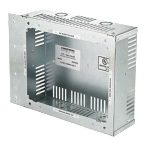
TPS-12L and TPS-12G-L wall mounted touchpanels. The table below lists all of the parts included with the BB-12L. Supplied Components The mounted view of the BB-12L is shown in the following diagram. BB-12L Mounted View (Optional Cover Plate Attached) Installation Guide - DOC. 6357A ®... -
Page 6: Cover Plate
Wall Mount Back Box The dimensions of the BB-12L are shown in the following diagram. Dimensional Drawing (Fully Assembled without Cover Plate) 12.78 in (32.45 cm) (34.92 cm) BACK BOX (ASSEMBLED) (33.72 cm) COVER PLATE 2 • Wall Mount Back Box: BB-12L 10.87 in... -
Page 7: Installation
3. Attach upper and lower mounting brackets to the enclosure assembly using supplied (4) #6-32 x 1/4” screws. ENCLOSURE ASSEMBLY (4500077) FOR TOUCHPANEL QTY. 1 #08-8B 1/4"L SELF TAPPING SCREW (2007277) FOR GROUND PURPOSES Wall Mount Back Box Wall Mount Back Box: BB-12L • 3... -
Page 8: Mounting
• Level • 1. Position the back box to the front edge of the stud and align it as even and as flush as possible. 2. Use the level and verify that the back box is horizontal. Leveling must be done before proceeding. - Page 9 NOTE: Confirm that the eight tapped holes on the front of the back box are exposed to accept the touchpanel mounting screws. NOTE: Cut the drywall to the inside edge of the front of the back box and notch where needed for the screwholes.
-
Page 10: Other Mounting Option Accessories
This product is Listed to applicable UL Standards and requirements by Underwriters Laboratories Inc. As of the date of manufacture, the BB-12L has been tested and found to comply with specifications for CE marking. Future Updates As Crestron adds improvements to the BB-12L, additional information may be made available as manual updates. -
Page 11: Return And Warranty Policies
Purchasers should inquire of the dealer regarding the nature and extent of the dealer's warranty, if any. CRESTRON shall not be liable to honor the terms of this warranty if the product has been used in any application other than that for which it was intended, or if it has been subjected to misuse, accidental damage, modification, or improper installation procedures. - Page 12 Crestron Electronics, Inc. Installation Guide – DOC. 6357A 15 Volvo Drive Rockleigh, NJ 07647 (2013440) Tel: 888.CRESTRON 11.05 Fax: 201.767.7576 Specifications subject to www.crestron.com change without notice.
Need help?
Do you have a question about the BB-12L and is the answer not in the manual?
Questions and answers