Table of Contents
Advertisement
Quick Links
Advertisement
Table of Contents

Subscribe to Our Youtube Channel
Related Manuals for Crestron BB-2000L


Summary of Contents for Crestron BB-2000L
- Page 1 Crestron BB-2000L Wall Mount Back Box Installation Guide...
- Page 2 This document was prepared and written by the Technical Documentation department at: Crestron Electronics, Inc. 15 Volvo Drive Rockleigh, NJ 07647 1-888-CRESTRON All brand names, product names and trademarks are the property of their respective owners. ©2003 Crestron Electronics, Inc.
-
Page 3: Table Of Contents
Crestron BB-2000L Contents Wall Mount Back Box: BB-2000L Description... 1 Installation ... 2 Assembly ... 2 Mounting ... 3 Other Mounting Option Accessories ... 5 Further Inquiries ... 6 Future Updates... 6 Return and Warranty Policies ... 7 Merchandise Returns / Repair Service ... 7 CRESTRON Limited Warranty... -
Page 5: Wall Mount Back Box: Bb-2000L
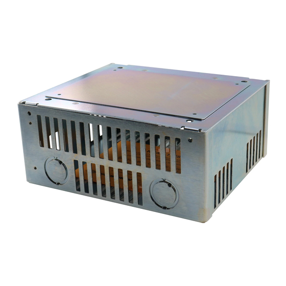
Wall Mount Back Box: BB-2000L Description The BB-2000L is a pre-construction mounting option for the TPS-2000L Compact Video Touchpanel. The table below lists all parts included with the BB-2000L. Supplied Components The mounted view and mounting plate dimensions (for touchpanel insertion) of the BB-2000L are shown below. -
Page 6: Installation
Complete the following assembly procedure in the order provided (refer to illustration below). Assembly View 2 • Wall Mount Back Box: BB-2000L #2 Phillips tip screwdriver 1. Remove knockouts as required. 2. Attach the supplied self-tapping pan Phillips (8B x ¼” length) screw to the wall mount enclosure for grounding. -
Page 7: Mounting
1. Position assembly to the front edge of the stud and align it as even and as flush as possible. 2. Use the level and verify that the back box is horizontal. Leveling must be done before proceeding. 3. Attach the assembly to the left or right side of the stud with standard drywall screws or nails (supplied by other). - Page 8 (160 mm) NOTE: Confirm that the four tapped holes in the mounting plate are exposed to accept the touchpanel mounting screws. Mounted BB-2000L with Optional Cover Plate Installed 4 • Wall Mount Back Box: BB-2000L (135 mm) 6. Complete the installation by either installing the touchpanel, leaving the hole open (if permitted by local building codes), or installing the supplied cover plate with #6-32 x 1½”...
-
Page 9: Other Mounting Option Accessories
If too much of the cover plate is exposed after the drywall is cut, you may need to patch the area. Crestron provides the following accessories: The manuals for the MMK-2000L and TMK-2000L are available for review from the Downloads | Product Manuals section of the Crestron website (www.crestron.com). Installation Guide - DOC. 5973A •... -
Page 10: Further Inquiries
Wall Mount Back Box Further Inquiries If after reviewing this Installation Guide for the BB-2000L, you cannot locate specific information or have questions, please take advantage of Crestron's award winning customer service team by calling: Future Updates As Crestron adds improvements to the BB-2000L, additional information may be made available as manual updates. -
Page 11: Return And Warranty Policies
Purchasers should inquire of the dealer regarding the nature and extent of the dealer's warranty, if any. CRESTRON shall not be liable to honor the terms of this warranty if the product has been used in any application other than that for which it was intended, or if it has been subjected to misuse, accidental damage, modification, or improper installation procedures. - Page 12 Crestron Electronics, Inc. Installation Guide – DOC. 5973A 15 Volvo Drive Rockleigh, NJ 07647 01.03 Tel: 888.CRESTRON Fax: 201.767.7576 Specifications subject to www.crestron.com change without notice.
Need help?
Do you have a question about the BB-2000L and is the answer not in the manual?
Questions and answers