Advertisement
Quick Links
Advertisement

Subscribe to Our Youtube Channel
Related Manuals for WATSON 360.394.1300


Summary of Contents for WATSON 360.394.1300
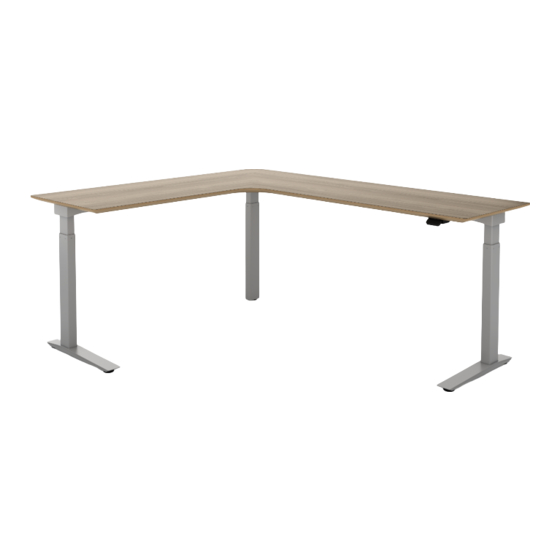
- Page 1 ASSEMBLY Essential Three-Leg Desk 360.394.1300 watsonfurniture.com V.21.0 06/2021...
-
Page 2: Important Safety Instructions
Important Safety Instructions This product is for commercial use only. Maximum intended load for this desk is 250 lbs (113 kg) When using an electrical furnishing, basic precautions should always be followed, including the following: Read all instructions before using (this furnishing). DANGER - To reduce the risk of electric shock: Always unplug this furnishing from the electrical outlet before cleaning. - Page 3 If Using Optional Utility Power - The electrical desk plug must be plugged into the utility power when present. This product is for use on a nominal 120-volt circuit and has a grounding plug that looks like the plug illustrated in sketch A (see Figure 77.1).
- Page 4 Essential Three-Leg Desk Components Extended Corner Desk Surface Outer Support Rail Inner Support Rail Shroud Brackets Shroud Plates Outer Desk Feet Mid-Leg Foot Outer Support Rail End Brackets Inner Support Rail End Bracket Motor Cables Embedded Two- Undersurface Button Switch Paddle Switch DL6 Lifting Column DL5 Lifting Column...
- Page 5 Hardware M6-1.0 X 12MM Button Head M6-1.0 Nylock Nut, M6-1.0 X 40MM Screw, Black or Zinc dependent Zinc (888152) Button Head Screw, on desk color (125285/125290) Zinc (125293) #8 X 1/2 Pan M6-1.00 X 6MM #8 X 1-1/4 Flat #8 X 5/8 Flat Cable Clips Head Screw, Black Button Head Screw...
- Page 6 Support Rail Assembly Assemble on a clean soft surface, ensuring area is free of debris. Place support rail segments top down. Verify orientation of support rails matches the handed rail assembly mounting pattern on desk surface (a.). Align the inner rail end tab with the slot on the end of the outer rail.
- Page 7 Attach Legs to Support Rail Assembly Slide lifting columns into the ends of the support rail as shown (a.). Attach legs with (8) button head screws, (2) on each side of each leg (b.). M6-1.0 X 12MM Button Head Screw, Black or Zinc dependent on desk color (125285/125290) 7 ESSENTIAL THREE-LEG DESK ASSEMBLY INSTRUCTIONS...
- Page 8 Attach Optional Shrouds Some desk leg finishes require a steel shroud. If a shroud is included, hold the padded side of the shroud plates against the inner face of the lifting columns (a.) and slide the shroud brackets over the lifting columns and plates (b.). Attach Desk Feet Attach the mid-leg foot to the center leg with (4) button head screws.
- Page 9 Control Box Assembly Flip the base assembly right side up. Plug the power cable into the control box, and route power cord through the strain relief channel on the underside of the control box (a.). Place the assembly centered on the outer support rail, and route the power cable through the rear cutout in the side of the support rail, as shown.
- Page 10 Control Box Wiring Diagrams After securing the control box to the support rail, plug in lifting column power cables into ports 1, 2, & 3 and the Anti-Collision Dongle into port A1. Feed switch cable through the support rail cutout and plug into port A2 (a.). *Detailed steps for switches steps 5 &...
- Page 11 Support Rail Cable Routing After securing all lifting column cables to the control box, plug the other ends into their respective lifting column, routing the longest cable out through the cutout in the side of the outer support rail, and back into the cutout in the inner support rail.
- Page 12 Mount Desk Surface Coil any excess cables in the support rail trough, ensuring they are inside the support rail. Rotate worksurface onto support rail assembly and align brass inserts with mounting slots on support rails. 12 ESSENTIAL THREE-LEG DESK ASSEMBLY INSTRUCTIONS...
- Page 13 Secure Desk Surface to Base Attach worksurface to support rail assembly with (14) button head screws, (4) screws per outer leg, and (6) screws for the mid-leg. M6-1.0 X 12MM Button Head Screw, Black or Zinc dependent on desk color (125285/125290) 13 ESSENTIAL THREE-LEG DESK ASSEMBLY INSTRUCTIONS...
- Page 14 Two-Button Embedded Switch Switch options include an embedded two-button switch or an undersurface paddle switch. The two-button switch will have a designated cutout in the surface to mount the switch inside. Insert the switch assembly into the cutout, and secure with (2) flat head screws.
- Page 15 Attach Cable Clips Secure single-sided cable clips to the undersurface with (1) pan head screw per clip. Cable Clips #10 X 5/8 Pan (486911) Head Screw, Zinc (122800) 15 ESSENTIAL THREE-LEG DESK ASSEMBLY INSTRUCTIONS...
- Page 16 Attach Support Rail End Covers Attach support rail end covers to outer legs and the short end cover to mid-leg using the remaining brass inserts with (2) button head screws per cover. M6-1.0 X 12MM Button Head Screw, Black or Zinc dependent on desk color (125285/125290) 16 ESSENTIAL THREE-LEG DESK ASSEMBLY INSTRUCTIONS...
- Page 17 Power Test & Leveling Plug power cord into 110V AC receptacle and depress the down arrow once to initialize desk. The desk will travel down a fraction of an inch then stop. The desk is now ready to travel up and down using the switch. Place the desk in the workstation setting maintaining a minimum 1”...
Need help?
Do you have a question about the 360.394.1300 and is the answer not in the manual?
Questions and answers