
Related Manuals for Basler BE1-81O/U


Summary of Contents for Basler BE1-81O/U
- Page 1 INSTRUCTION MANUAL DIGITAL FREQUENCY RELAY BE1-81O/U Publication: 9137300990 Revision: J 10/07...
- Page 3 INTRODUCTION This instruction manual provides information about the operation and installation of the BE1-81O/U Digital Frequency Relay. To accomplish this, the following information is provided: • General Information and Specifications • Controls and Indicators • Functional Description • Installation • Testing...
- Page 4 October 2007 CONFIDENTIAL INFORMATION of Basler Electric, Highland Illinois, USA. It is loaned for confidential use, subject to return on request, and with the mutual understanding that it will not be used in any manner detrimental to the interest of Basler Electric.
- Page 5 REVISION HISTORY The following information provides a historical summary of the changes made to the BE1-81O/U instruction manual (9137300990). Revisions are listed in reverse chronological order. Manual Revision and Date Change • J, 10/07 Added manual part number and revision to all footers.
- Page 6 This page intentionally left blank. BE1-81O/U Introduction 9137300990 Rev J...
-
Page 7: Table Of Contents
Auxiliary Relay Outputs ........................ 3-5 Power Supply..........................3-5 Power Supply Status Output ......................3-5 Target Indicators........................... 3-5 SECTION 4 • INSTALLATION........................4-1 INTRODUCTION..........................4-1 OPERATING PRECAUTIONS......................4-1 MOUNTING............................4-1 CONNECTIONS..........................4-15 MAINTENANCE ..........................4-16 STORAGE............................4-16 9137300990 Rev J BE1-81O/U Introduction... - Page 8 TEST EQUIPMENT..........................5-1 OPERATIONAL TEST ........................5-1 Frequency Selector Settings ......................5-2 Definite Time Delay - Cycles ......................5-3 Definite Time Delay - Seconds ..................... 5-3 Undervoltage Inhibit........................5-3 Setpoint 2, 3, and 4 Testing......................5-4 BE1-81O/U Introduction 9137300990 Rev J...
-
Page 9: Section 1 • General Information
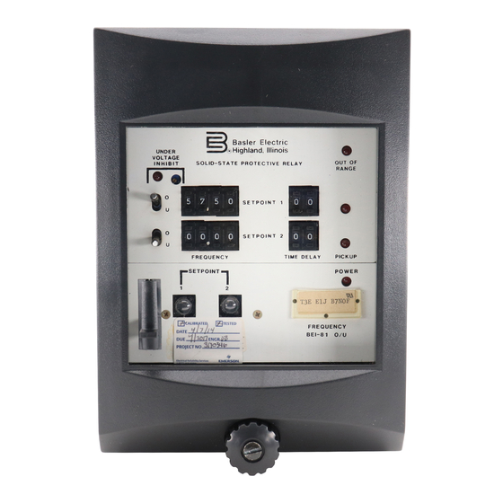
Each frequency setpoint has a setting range of 40 to 70 hertz and can be switch selected to detect over- frequency or underfrequency. BE1-81O/U relays with one or two setpoints are supplied in an S1 case. Relays with three or four setpoints are supplied in an M1 case. - Page 10 Figure 1-1. Style Number Identification Chart For example, if the BE1-81O/U style number was T3E E1J A9N2F, the relay would have the following features and options. T-------------Single-phase sensing input 3-------------100/120 Vac, 40 to 70 Hz nominal sensing range E ------------One normally-open output relay per setpoint...
-
Page 11: Specifications
SPECIFICATIONS BE1-81O/U electrical and physical specifications are listed in the following paragraphs. Sensing Input Voltage Range: 40 to 132 Vac Frequency Detection Range: 30 to 80 Hz (Revision D and subsequent) 35 to 80 Hz (Revision C and previous) Computation Range:... -
Page 12: Frequency Setpoint
Withstands 15 G in each of three mutually perpendicular axes Vibration: Withstands 2 G in each of three mutually perpendicular axes swept over the range of 10 to 500 Hz for a total of six sweeps, 15 minutes each sweep. BE1-81O/U General Information 9137300990 Rev J... -
Page 13: Temperature Ratings
S1 (See Section 4, Installation for case dimensions.) Three or Four Setpoints: M1 (See Section 4, Installation for case dimensions.) Weight S1 Case: 13 lb (5.90 kg) net M1 Case: 18 lb (8.16 kg) net 9137300990 Rev J BE1-81O/U General Information... - Page 14 Figure 1-2. Inverse Time Overfrequency Characteristic Curves BE1-81O/U General Information 9137300990 Rev J...
- Page 15 100.00 10.00 1.00 0.10 0.01 Frequency Difference From Setpoint (Hz) D2645-09 04-07-97 Figure 1-3. Inverse Time Underfrequency Characteristic Curves 9137300990 Rev J BE1-81O/U General Information...
- Page 16 This page intentionally left blank. BE1-81O/U General Information 9137300990 Rev J...
-
Page 17: Section 2 • Controls And Indicators
Undervoltage Inhibit Control. Relay operation is inhibited when the sensed voltage decreases below the setting of this multi-turn potentiometer. The Undervoltage Inhibit Control has a setting range of 40 to 120 Vac. The BE1-81O/U is delivered with the control set at 80 Vac. -
Page 18: Circuit Board
1, 10, or 100. With the cradle assembly withdrawn from the case, the three-section Selector Switches are accessed at the right side of the cradle assembly. Figure 2-2 illustrates the location of S7 on a BE1-81O/U relay with two setpoints. -
Page 19: Multiplier Settings
S7-3 either selects cycles or seconds as the unit of measure for the definite time delay. S7-3 is placed in the up position to select cycles. The down position of S7-3 selects seconds. 9137300990 Rev J BE1-81O/U Controls and Indicators... - Page 20 This page intentionally left blank. BE1-81O/U Controls and Indicators 9137300990 Rev J...
-
Page 21: Section 3 • Functional Description
SECTION 3 • FUNCTIONAL DESCRIPTION INTRODUCTION The Digital Frequency Relay, BE1-81O/U, has one to four frequency setpoints for protecting an ac source from underfrequency and overfrequency conditions within the limits of 40 to 70 hertz. When the BE1- 81O/U senses an underfrequency or overfrequency condition, an output relay energizes after a selectable time delay. - Page 22 Figure 3-1. BE1-81O/U Functional Block Diagram BE1-81O/U Functional Description 9137300990 Rev J...
-
Page 23: Maximum Period Difference Logic
0.008 seconds (output relay delay). The Pickup LED remains lit until the frequency condition is corrected. When the sensed frequency returns to normal for three cycles, the Pickup LED and output relay reset. 9137300990 Rev J BE1-81O/U Functional Description... - Page 24 10, or 100. NOTE Earlier BE1-81O/U relays with timing option E1 had a timing range of 3 to 99 cycles and did not include Selector Switch S7. Earlier relays with timing option E2 had a timing range of 3 to 99 cycles.
-
Page 25: Relay Outputs
Power Supply BE1-81O/U internal circuitry is powered by one of three wide-range power supplies. Power supply voltage ratings are listed in Table 1-1. - Page 26 This page intentionally left blank. BE1-81O/U Functional Description 9137300990 Rev J...
-
Page 27: Section 4 • Installation
Because the BE1-81O/U relay is of solid-state design, it may be mounted at any convenient angle. The BE1-81O/U relay is supplied in an S1 or M1 case. Relays with one setpoint (option 1-6) or two setpoints (option 1-7) are supplied in an S1 case. Relays with three setpoints (option 1-8) or four setpoints (option 1-9) are supplied in an M1 case. - Page 28 Figure 4-1. S1 Case, Panel Cutting Diagram, Semi-Flush Mounting BE1-81O/U Installation 9137300990 Rev J...
- Page 29 Figure 4-2. S1 Case, Panel Cutting/Drilling Diagram, Projection Mounting, Rear View 9137300990 Rev J BE1-81O/U Installation...
- Page 30 D2853-21 06-15-99 Figure 4-3. S1 Case (Cover) Dimensions, Front View BE1-81O/U Installation 9137300990 Rev J...
- Page 31 Figure 4-4. S1 Case Dimensions, Rear View 9137300990 Rev J BE1-81O/U Installation...
- Page 32 D2853-22 06-15-99 Figure 4-5. S1 Case Dimensions, Semi-Flush Mounting, Side View BE1-81O/U Installation 9137300990 Rev J...
- Page 33 Figure 4-6. S1 Case Dimensions, Projection Mounting, Side View 9137300990 Rev J BE1-81O/U Installation...
- Page 34 5.69 (144.5) .25 (6.4) DIA. 2.84 4 PLACES (72.1) 14.25 14.63 (362.0) (371.5) 7.13 7.31 (181.0) (185.7) 3.03 (77.0) D1427-11 6.06 2-16-93 (154.0) Figure 4-7. M1 Case, Panel Cutting Diagram, Semi-Flush Mounting BE1-81O/U Installation 9137300990 Rev J...
- Page 35 Figure 4-8. M1 Case, Panel Cutting/Drilling Diagram, Projection Mounting, Double-Ended, Rear View 9137300990 Rev J BE1-81O/U Installation...
- Page 36 Figure 4-9. M1 Case, Cutting/Drilling Diagram, Projection Mounting, Single-Ended, Rear View 4-10 BE1-81O/U Installation 9137300990 Rev J...
- Page 37 D2856-02 06-15-99 Figure 4-10. M1 Case (Cover) Dimensions, Front View 9137300990 Rev J BE1-81O/U Installation 4-11...
- Page 38 5.56 (141.3) D1427-09 07-09-93 14.69 (373.1) Figure 4-11. M1 Case Dimensions, Rear View 4-12 BE1-81O/U Installation 9137300990 Rev J...
- Page 39 Figure 4-12. M1 Case Dimensions, Semi-Flush Mounting, Side View 9137300990 Rev J BE1-81O/U Installation 4-13...
- Page 40 PANEL CASE DETAIL A-A SHOWING THE ADDITION OF WASHERS OVER THE BOSS TO TIGHTEN THE RELAY AGAINST THE PANEL. D2856-21 06-15-99 Figure 4-13. M1 Case Dimensions, Projection Mounting, Side View 4-14 BE1-81O/U Installation 9137300990 Rev J...
-
Page 41: Connections
Incorrect wiring may result in damage to the relay. Except for the ground wire, connections should be made with wire no smaller than 14 AWG. Typical internal connections are shown in Figure 4-14. External connections are shown in Figures 4-15 and 4-16. Figure 4-14. Internal Relay Connections 9137300990 Rev J BE1-81O/U Installation 4-15... -
Page 42: Maintenance
Figure 4-15. Typical DC Connections Figure 4-16. Typical AC Sensing Connections MAINTENANCE BE1-81O/U relays require no preventative maintenance other than a periodic operational check. If the relay fails to function properly, contact Technical Sales Support at Basler Electric to coordinate repairs. STORAGE This protective relay contains aluminum electrolytic capacitors which generally have a life expectancy in excess of 10 years at storage temperatures less than 40°C (104°F). -
Page 43: Section 5 • Testing
SECTION 5 • TESTING INTRODUCTION Procedures in this section are used for testing and adjusting a BE1-81O/U relay for the desired operation in a protective scheme. If a relay fails a test, or an adjustment discloses a faulty relay, refer to Section 6. -
Page 44: Frequency Selector Settings
Figure 5-1. BE1-81O/U Test Setup Frequency Selector Settings 1. Connect the relay as shown in Figure 5-1. 2. Adjust the front panel, setpoint 1 controls to the following settings. Over/Under Selector Switch: Under (U) position Frequency Selector Switch: 51.11 3. Apply operating power to the relay. -
Page 45: Definite Time Delay - Cycles
Time Delay Selector Switch: 25 3. Apply operating power to the relay. 4. Apply 60 Hz voltage to the relay sensing input. The level of voltage must exceed the setting of the adjustable, front panel Undervoltage Inhibit control. 9137300990 Rev J BE1-81O/U Testing... -
Page 46: Setpoint 2, 3, And 4 Testing
5. Decrease the level of the sensing input voltage until it is considerably less than the Undervoltage Inhibit control setting. (BE1-81O/U relays are delivered with an undervoltage inhibit setting of 80 Vac.) The Undervoltage Inhibit indicator should light. 6. Decrease the frequency of the sensing input voltage to 59 Hz. The setpoint 1 Pickup indicator should not light and the setpoint 1 output relay should not trip. - Page 47 ROUTE 143, BOX 269 HIGHLAND, IL 62249 USA http://www.basler.com, info@basler.com PHONE +1 618-654-2341 FAX +1 618-654-2351...
Need help?
Do you have a question about the BE1-81O/U and is the answer not in the manual?
Questions and answers