
Related Manuals for Basler BE1-27


Summary of Contents for Basler BE1-27
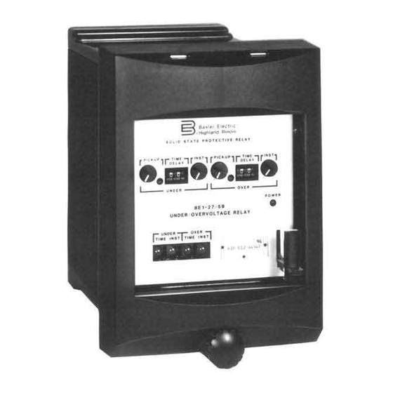
- Page 1 INSTRUCTION MANUAL UNDERVOLTAGE, OVERVOLTAGE, AND UNDER/OVERVOLTAGE RELAYS BE1-27, BE1-59, AND BE1-27/59 Publication Number: 9 1706 00 990 Revision: 11/99...
- Page 2 INTRODUCTION The purpose of this Instruction Manual is to furnish information concerning the operation and installation of this device. To accomplish this, the following is provided. •Specifications •Functional Characteristics •Operational Tests •Mounting Information WARNING! TO AVOID PERSONAL INJURY OR EQUIPMENT DAMAGE, ONLY QUALIFIED PERSONNEL SHOULD PERFORM THE PROCEDURES PRESENTED IN THIS MANUAL.
- Page 3 The availability and design of all features and options are subject to modification without notice. Should further information be required, call Basler Electric Company, Highland, Illinois. INTRODUCTION...
-
Page 4: Table Of Contents
CONTENTS SECTION 1 GENERAL INFORMATION ........1-1 Purpose . - Page 5 CONTENTS - Continued SECTION 6 MAINTENANCE ......... . . 6-1 General .
-
Page 6: Section 1 • General Information
During motor start-up, a low terminal voltage condition will inhibit the motor from reaching rated speed. The BE1-27 undervoltage relay will detect this low voltage condition and trip. Critical applications requiring continuous motor operation and applications where overloads during start- up may be maintained for a given time period, usually have a definite time or inverse time delay characteristic incorporated to avoid unnecessary tripping during low voltage dips. -
Page 7: Transformer Protection
The model number BE1-27/59 designates the relay as a Basler Electric Class 100 Under/Overvoltage Relay. -
Page 8: Sample Style Number
SAMPLE STYLE NUMBER The style number identification chart above illustrates the manner in which a relay's style number is determined. For example, if the model number is BE1-27/59 and the style number is A3F E1J AOS1F the device has the following features:... -
Page 9: Specifications
SPECIFICATIONS Voltage Sensing Nominally rated at 50/60 Hz, (120/240 V or 100/200 V) with a maximum continuous voltage rating of 360 V (120 V nominal ) or 480 V (240 V nominal ) at a burden less than 1 VA per phase. - Page 10 Definite Time Accuracy Within ± one half of the least significant digit time plus 50 ms. Inverse Time Inverse curve types are defined by the Style Chart and are represented by the curves shown in Section 3. Inverse time is adjustable from 01 to 99 in increments of 01.
-
Page 11: Controls And Indicators
SECTION 2 • HUMAN-MACHINE INTERFACE CONTROLS AND INDICATORS The following table is referenced to Figure 2-1. Table 2-1. Controls And Indicators Locator Control or Indicator Function UNDER PICKUP Control Establishes setpoint for the timed undervoltage function. Continuously adjustable over the range defined by the style number. - Page 12 Target Reset Lever Linkage extending through bottom of front (Optional) cover pushed to reset the magnetically latching target indicators. OVER PICKUP Indicator Illuminated to indicate that the timed overvoltage pickup setting is exceeded. Target Indicators Magnetically latching indicators are tripped to (Optional) red to indicate that an undervoltage or overvoltage output relay has been energized.
-
Page 13: Section 3 • Functional Description
SYSTEM VOLTAGES The BE1-27, BE1-59, and BE1-27/59 relays are available with three sensing input ranges. The 55 to 160V range is intended for use with nominal system voltages of 120V or 69V (120/ 3). The 110 to 320 volt range is intended for use with nominal system voltages of 240V, 208V (120 X 3), or 277V (480/ 3). -
Page 14: Step-Down Transformers
STEP-DOWN TRANSFORMER The monitored system voltage is applied to the primary of an internal potential transformer and stepped down to internal circuit levels. The transformer provides a high degree of isolation. LOW-PASS FILTER AND FULL WAVE RECTIFIER The output of the step-down transformer is low-pass filtered to prevent undesired response to high-frequency noise. - Page 15 Range 2 Range 3 Range 4 D2857-23.vsd Voltage Difference From Pickup 11-22-99 Figure 3-2. Undervoltage, Short Inverse Timing Characteristic Curve 1 0 0 0 1 0 0 Range 2 Range 3 Range 4 D2857-24.vsd Voltage Difference From Pickup 11-22-99 Figure 3-3. Undervoltage, Medium Inverse Timing Characteristic Curve FUNCTIONAL DESCRIPTION...
- Page 16 1000 Range 2 Range 3 Range 4 D2857-25.vsd Voltage Difference From Pickup 11-22-99 Figure 3-4. Undervoltage, Long Inverse Timing Characteristic Curve 100.0 10.0 Range 2 Range 3 Range 4 D2750-14.vsd Voltage Difference From Pickup 11-22-99 Figure 3-5. Overvoltage, Short Inverse Timing Characteristic Curve FUNCTIONAL DESCRIPTION...
- Page 17 1000.0 100.0 10.0 Range 2 Range 3 Range 4 Voltage Difference From Pickup D2750-15.vsd 11-22-99 Figure 3-6. Overvoltage, Medium Inverse Timing Characteristic Curve 1000.0 100.0 10.0 Range 2 Range 3 Range 4 D2750-16.vsd Voltage Difference From Pickup 11-22-99 Figure 3-7. Overvoltage, Long Inverse Timing Characteristic Curve FUNCTIONAL DESCRIPTION...
-
Page 18: Targets
Target indicators must be manually reset. POWER SUPPLY Basler Electric enhanced the power supply design for unit case relays. This new design created three, wide range power supplies that replace the four previous power supplies. Style number identifiers for these power supplies have not been changed so that customers may order the same style numbers that they ordered previously. -
Page 19: Section 4 • Installation
Visually inspect the relay for damage that may have occurred during shipment. If there is evident damage, immediately file a claim with the carrier and contact the Basler Electric Regional Sales Office, your Sales Representative, or the Sales Representative at Basler Electric, Highland, Illinois. -
Page 20: Connections
CONNECTIONS Incorrect wiring may result in damage to the relay. Typical internal connections are shown in Figures 4-13 through 4-15. Typical ac connections are shown in Figure 4-16. Typical dc connections are shown in Figure 4-17. Be sure to check model and style number against the options listed in the Style Number Identification Chart before connecting and energizing a particular relay. - Page 21 Figure 4-2 . S1 Case, Single-Ended, Semi-Flush Mounting, Outline Dimensions, Side View INSTALLATION...
- Page 22 Figure 4-3 . S1 Case, Single-Ended, Projection Mount, Outline Dimensions, Side View INSTALLATION...
- Page 23 Figure 4-4 . S1 Case, Double-Ended, Semi-Flush Mounting, Outline Dimensions, Side View INSTALLATION...
- Page 24 Figure 4-5 . S1 Case, Double-Ended, Projection Mount, Outline Dimensions, Side View INSTALLATION...
- Page 25 Figure 4-6 . S1 Case, Single-Ended, Semi-Flush Mounting, Outline Dimensions, Rear View INSTALLATION...
- Page 26 Figure 4-7. S1 Case, Single-Ended, Projection Mount, Outline Dimensions, Rear View INSTALLATION...
- Page 27 Figure 4-8 . S1 Case, Double-Ended, Semi-Flush Mounting, Outline Dimensions, Rear View INSTALLATION...
- Page 28 Figure 4-9 . S1 Case, Double-Ended, Projection Mount, Outline Dimensions, Rear View 4-10 INSTALLATION...
- Page 29 Figure 4-10 . S1 Case, Panel Drilling Diagram, Semi-Flush Mounting INSTALLATION 4-11...
- Page 30 Figure 4-11 . S1 Case, Single-Ended, Projection Mount, Panel Drilling Diagram, Rear View 4-12 INSTALLATION...
- Page 31 Figure 4-12 . S1 Case, Double-Ended, Projection Mounting, Panel Drilling Diagram, Rear View INSTALLATION 4-13...
- Page 32 Figure 4-13. BE1-27 Internal Connections 4-14 INSTALLATION...
- Page 33 Figure 4-14 . BE1-59 Internal Connections INSTALLATION 4-15...
- Page 34 Figure 4-15 . BE1-27/59 Internal Connections 4-16 INSTALLATION...
- Page 35 BE1-27 BE1-59 BE1-27/59 D2816-13 05-29-98 Figure 4-16 . Typical AC Connections INSTALLATION 4-17...
- Page 36 + T R I P B U S A U X I L I A R Y C O N T A C T S 27/59 27/59 27/59 27/59 27/59 T A R G E T T A R G E T T A R G E T T A R G E T I O V...
-
Page 37: Operational Test Procedure
SECTION 5 • TESTS AND ADJUSTMENTS GENERAL Procedures in this section are for use in testing and adjusting a relay for the desired operation in a protective scheme. If a relay fails an operational test, or is an adjustment discloses a faulty relay, refer to Section 6. REQUIRED TEST EQUIPMENT Minimum test equipment required for relay testing and adjustment is listed below. - Page 38 NOTE Results assume normally open output contacts. Test indicator states will be opposite for normally closed output contacts. OPERATING P O W E R BE1-27, 59, 27/59 S O U R C E D2816-15 05-29-98 Figure 5-1. Pickup and Dropout Test Circuit Diagram...
- Page 39 Figure 5-2. Timing Test Circuit Diagram RESULTS: In units with Sensing Input Range 2 the OVER PICKUP indicator is illuminated as well as the timed and instantaneous overvoltage test indicators. In units with Sensing Input Range 3 or 4, all pickup and test indicators will be extinguished. Table 5-1.
-
Page 40: Timing
326.4 for Sensing Input Range 4. This concludes the pickup test for Relay Model BE1-27. NOTE Steps 7 and 8 apply only to overvoltage functions. Step 7. Slowly increase the T1 voltage until the OVER PICKUP indicator and the timed and instantaneous overvoltage test indicators illuminate. - Page 41 Table 5-2. Timing Test Results Timing Type Column 1 Column 2 Instantaneous 50 ms or less 50 ms or less Definite Less than 0.2 sec 9.8 - 10.0 sec Under Over Under Over Short Inverse 0.087 to 0.187 sec 0.092 to 0.192 sec 6.231 to 6.687 sec 6.557 to 7.247 sec Medium Inverse 0.292 to 0.392 sec...
-
Page 42: Section 6 Maintenance
SECTION 6 • MAINTENANCE GENERAL Basler relays are static devices which require no preventive maintenance other than a periodic operational check. The operational test procedure of Section 5 provides an adequate check to verify proper operation of the relay. Most components are on conformally coated PC boards. In-house replacement of individual components may be difficult and should not be attempted unless appropriate equipment and qualified personnel are available. -
Page 43: Changes
SECTION 7 • MANUAL CHANGE INFORMATION CHANGES This section contains information concerning the previous editions of the manual. The substantive changes to date are summarized below. Table 7-1. Summary of Changes Revision Summary of Changes ECA/ECO/Date A and B Information on these revisions is not available at this time. 8401 &...
Need help?
Do you have a question about the BE1-27 and is the answer not in the manual?
Questions and answers