
Related Manuals for Basler BE1-79M


Summary of Contents for Basler BE1-79M
- Page 1 INSTRUCTION MANUAL MULTIPLE SHOT RECLOSING RELAY BE1-79M P0046-01 Publication: 9170100990 Revision: K 11/06...
- Page 3 INTRODUCTION This manual provides information concerning the operation and installation of the BE1-79M Multiple Shot Reclosing Relay. To accomplish this, the following is provided. • Specifications • Functional description • Mounting information • Operational Test Procedure WARNING! To avoid personal injury or equipment damage, only qualified personnel should perform the procedures presented in this manual.
- Page 4 The availability and design of all features and options are subject to modification without notice. Should further information be required, contact Basler Electric Company, Highland, Illinois. BASLER ELECTRIC...
- Page 5 • Moved sensing input power module from outside the case to inside the case Added Section 7, Difference Data to support BE1-79M Relay revision D and previous. Changed Style Number Identification Chart first character from A to B in response to ECA 12237, changed operational Test Procedure, Section 4 to improve procedures and correct typographical error, and added old Style Number Identification Chart to Section 7.
- Page 6 Revision Summary of Changes J/06-98 Deleted reference to Service Manuals. Replaced Power Supply paragraph on page 3-6 starting with "Basler Electric enhanced the power supply...” Deleted Figure 3-4 and added Table 3-3. Corrected the Figure numbering following Figure 3-4. Changed the burden data for new power supply in Table 1-2.
-
Page 7: Table Of Contents
Data Retention ....................3-12 Clearing Stored Data ..................3-13 SECTION 4 INSTALLATION ......................4-1 General ........................4-1 Relay Operating Precautions ...................4-1 Dielectric Test ......................4-1 Mounting ........................4-1 Connections......................4-1 SECTION 5 TESTS AND ADJUSTMENTS ................5-1 General ........................5-1 Required Test Equipment..................5-1 Operational Test Procedure ..................5-1 BE1-79M Introduction... - Page 8 Clearing Stored Data..................5-6 SECTION 6 MAINTENANCE......................6-1 General ........................6-1 In-House Repair .......................6-1 Storage ........................6-1 Test Plug........................6-1 BE1-79M Test Set....................6-2 General ......................6-2 SYNC Switch .....................6-2 52a Lamp (Red)....................6-2 52b Lamp (Green) .....................6-2 BE1-79M Test Set....................6-3 SECTION 7 DIFFERENCE DATA ....................7-1 General ........................7-1...
-
Page 9: Information
A third major factor to be considered in reclosing is supervisory control. Supervisory control allows the operator to maintain control of the system at all times. The BE1-79M has inputs available to bypass the instantaneous reclose attempt and to drive the relay to LOCKOUT inhibiting relay operation at any time. -
Page 10: Model And Style Number
Basler Electric, Class 100, Multiple Shot Reclosing Relay. Style Number Example The following style number identification chart illustrates the features and options for BE1-79M relays. For example, if the style number were BE1-79M B6A A6J C0L0F, the device would have the following features: BE1-79M... -
Page 11: Style Number Identification Chart
Figure 1-1. Style Number Identification Chart BE1-79M General Information... -
Page 12: Specifications
SPECIFICATIONS The BE1-79M Relay is available with the following features and capabilities. Contact Sensing The contact sensing circuits require user-supplied contacts with a Reclose Initiate minimum rating of 0.025 A at 250 Vdc. Sensing current is supplied by Breaker (52b) the relay in styles with isolated sensing. - Page 13 Capability (SWC) Tests for Protective Relays and Relay Systems. Impulse Test Qualified to IEC 255-5. GOST-R Certification GOST-R certified No. POCC US.ME05.B03391; complies with the relevant standards of Gosstandart of Russia. Issued by accredited certification body POCC RU.0001.11ME05. Weight 13 pounds Case Size BE1-79M General Information...
- Page 14 Z (High Range) 240 Vac 90 to 270 Vac 14.1 VA ∗ Type L power supply may initially require 14 Vdc to begin operating. Once operating, the voltage may be reduced to 12 Vdc and operation will continue. BE1-79M General Information...
-
Page 15: Human-Machine Interface
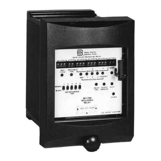
Figure 2-1 illustrates the location of controls and indicators on the front panel. Table 2-1 explains the call- outs shown in Figure 2-1. Table 2-2 lists the functions enabled per logic switch (S23) position. Figure 2-1. Location of Controls and Indicators BE1-79M Human-Machine Interface... - Page 16 Table 2-1. BE1-79M Controls and Indicators (Refer to Figure 2-1) Locator Control or Indicator Function Establish reclose time delays for corresponding time- RECLOSE TIME Controls (1, 2, 3) delayed reclosure attempts. Individually thumbwheel adjustable from 00.1 to 99.9 seconds in 00.1 second...
- Page 17 With Power-up to Reclose enabled, relay will close the breaker during power-up if relay was in RESET when powered-down and Pilot Initiate or Reclose Initiate is present during power- Table 2-2. Logic Switch (S23) Positions and Functions Enabled Position Functions Enabled 0∗∗ PR∗ PR∗ PR∗ PR∗ BE1-79M Human-Machine Interface...
- Page 18 Position Functions Enabled PR∗ PR∗ PR∗ PR∗ NOTES: ∗∗ Default position from factory Recognition Dropout Status LED Reset PR∗ Power-up to Reclose (Refer to Caution preceding Table 2-2) Memory Save BE1-79M Human-Machine Interface...
-
Page 19: Functional Description
SECTION 3 • FUNCTIONAL DESCRIPTION GENERAL The BE1-79M Multiple Shot Reclosing Relay is a microprocessor-based device, which responds to the state of external contacts. In responding, the Relay provides automatic reclosure once the circuit breaker has opened to de-energize the line. Refer to Section 1 for major factors to consider when establishing a reclosing philosophy. - Page 20 Figure 3-1. Functional Block Diagram BE1-79M Functional Description...
-
Page 21: Contact Interface
• Recognition Dropout - This function replaces the standard recognition dropout time of 17.5 milliseconds. The relay initiates a reclosing sequence if a 52b occurs within 200 milliseconds of an RI or PI. Figure 3-3 illustrates the recognition dropout timing relationship. BE1-79M Functional Description... -
Page 22: Thumbwheels
ITE, the instantaneous trip enable output contacts are closed while the breaker is closed if instantaneous trip enable switch 1 is in the enable position. Microprocessor The BE1-79M uses an 8-bit, low power, CMOS microprocessor which performs all timing and decision- making functions. Program Monitor Operation of the microprocessor is monitored by the program monitor. -
Page 23: Outputs
Changer (Optional) Power Supply Basler Electric enhanced the power supply design for unit case relays. This new design created three, wide range power supplies that replace the four previous power supplies. Style number identifiers for these power supplies have not been changed so that customers may order the same style numbers that they ordered previously. -
Page 24: Operational Characteristics
OPERATIONAL CHARACTERISTICS Due to the microprocessor-based design of the BE1-79M Multiple Shot Reclosing Relay, many of its operational characteristics are not apparent in the block diagram. The remaining information in this section is focused on the software-controlled features of the relay. -
Page 25: Reset
LOCKOUT, a state inhibiting relay operation, is produced by any of the following conditions: • Number of breaker openings exceeds the number of programmed reclosure attempts • Closure of the drive-to-lockout input contacts • Reclose failure • Duration of a reclosing sequence exceeds the maximum cycle setting BE1-79M Functional Description... -
Page 26: Reclosing Sequences
(manually or by other means) and remains closed for the duration of the reset time delay setting. Reclosing Sequences The BE1-79M Multiple Shot Reclosing Relay can generate three types of reclosing sequences. Each type is described in the following paragraphs and illustrated in Figures 3-5 and 3-6. •... - Page 27 ITEC = INSTANTANEOUS TRIP ENABLE OUTPUT CONTACTS CLOSED. S_E = INSTANTANEOUS TRIP SWITCH BE1-79M INST. = INSTANTANEOUS RECLOSURE (NO INTENTIONAL DELAY). D741-008 6-19-91 = RECLOSURE TIME DELAY SETTING. = UNKNOWN TIME INTERVAL < RESET TIME SETTING. Figure 3-5. Reclosing Sequences BE1-79M Functional Description...
- Page 28 Figure 3-6. Reclosing Flow Chart 3-10 BE1-79M Functional Description...
-
Page 29: Control Outputs And Special Contact Assignments
The REM counts and stores the cumulative number of attempts made in the following categories. • Instantaneous reclosures • First time-delayed reclosures • Second time-delayed reclosures • Third time-delayed reclosures • Pilot reclosures • Unsuccessful reclosures BE1-79M Functional Description 3-11... -
Page 30: Data Retrieval
2nd time delayed 3rd time delayed Pilot reclosure Unsuccessful reclosures None Any other NOTE: A "1" in the STATUS Indication column indicates LED is ON. Data Retention To retain data stored in memory and resume the event count, 3-12 BE1-79M Functional Description... -
Page 31: Clearing Stored Data
• Return front panel controls to their regular settings. • Place the relay back in service. It is a good practice to verify that the memory is cleared by repeating the data retrieval procedure and observing the results. BE1-79M Functional Description 3-13... - Page 32 This page intentionally left blank. 3-14 BE1-79M Functional Description...
-
Page 33: Installation
Visually inspect the relay for damage that may have occurred during shipment. If there is evidence of damage, immediately file a claim with the carrier and notify the Regional Sales Office, or contact the Sales Representative at Basler Electric, Highland, Illinois. - Page 34 (109.5) 3.03 .25 (6.35) DIA. (77.0) D492-005 4 PLACES 2-8-93 6.06 (154.0) MOUNT RELAY USING 4 #10 SCREWS NUMBERS IN PARENTHESES INDICATE METRIC DIMENSIONS (MILLIMETERS). ALL OTHER DIMENSIONS ARE IN INCHES. Figure 4-1. Panel Drilling Diagram (Flush Mounting) BE1-79M Installation...
- Page 35 P0046-06 Figure 4-2. S1 Case, Outline Dimensions, Front View BE1-79M Installation...
- Page 36 P0046-07 Figure 4-3. S1 Case, Double-Ended, Semi-Flush Mounting, Side View BE1-79M Installation...
- Page 37 CASE DETAIL A-A SHOWING THE ADDITION OF WASHERS OVER THE BOSS TO TIGHTEN THE RELAY AGAINST THE PANEL. P0046-08 Figure 4-4. S1 Case, Double-Ended, Projection Mounting, Side View BE1-79M Installation...
- Page 38 (25.4) (6.4) .75 (19.1) DIA. 2.63 20 PLACES (66.8) 5.25 D1427-05 (133.4) 2-17-93 NUMBERS IN PARENTHESES INDICATE METRIC DIMENSIONS (MILLIMETERS). ALL OTHER DIMENSIONS ARE IN INCHES. Figure 4-5. S1 Case, Double-Ended, Projection Mounting, Panel Drilling Diagram, Rear View BE1-79M Installation...
- Page 39 5.56 (141.3) D1427-24 7-9-93 8.68 (220.7) Figure 4-6. S1 Case, Double-Ended, Semi-Flush Mounting, Outline Dimensions, Rear View BE1-79M Installation...
- Page 40 5.56 (141.3) D1427-02 7-9-93 8.68 (220.7) Figure 4-7. S1 Case, Double-Ended, Projection Mounting, Outline Dimensions, Rear View BE1-79M Installation...
- Page 41 IF OPTION 1 IS 4 11-14-91 RI IS REPLACED BY RP. Figure 4-8. Sensing Input Connections OUTPUT CONTACT EXTERNAL CONNECTIONS Reclosing SOLID-STATE PROTECTIVE RELAY CASE GROUND #1 AND #2 OUTPUT CONTACT EXTERNAL CONNECTIONS D772-004 11-16-95 Figure 4-9. External Terminal Connections BE1-79M Installation...
- Page 42 K6 RELAY FAIL ALARM OUTPUT CONTACTS K7 PILOT RECLOSING OUTPUT CONTACTS (LOCKOUT AND RESET-3, 5, 7, 8) TC TRIP COIL CC CLOSING COIL BE1-79M D729-007 CONTROL CIRCUIT FUSING (IF USED) 5-13-91 MAY BE NO OR NC Figure 4-10. Typical Output Connections 4-10 BE1-79M Installation...
- Page 43 ISOLATED CONTACT J2 - 48Vdc OR 125Vdc. SENSING FIELD SELECTABLE LINK J2-4 J2-5 J2-2 J2-3 J2-1 PADDLE OPERATED SHORTING BAR ONLY IF NC/CONTACT IS USED. BLOCK LTC POWER SUPPLY BE1-79M D932-002 06-24-98 Figure 4-11. Typical Internal Connections BE1-79M Installation 4-11...
- Page 44 This page intentionally left blank. 4-12 BE1-79M Installation...
-
Page 45: Tests And Adjustments
1. If reset timer option is D, set RESET to 60. 2. If reclose time delay option is A7, set RECLOSE TIME 2 to 010 and RECLOSE TIME 3 to 015. 3. If reclose time delay option is A8, set PILOT TIME to 99. BE1-79M Tests and Adjustments... - Page 46 If the BLTC NC option is present, a continuity check should show continuity between terminals 1 and 2. If the BLTC NO option is present, a continuity check should NOT indicate continuity between terminals 1 and 2. BE1-79M Tests and Adjustments...
- Page 47 Press and release S6. In 1 second, the STATUS 1 LED should light, and there should be continuity between terminals 17 and 18. c. Press and release S6. In 1 second, the STATUS 2 LED should light, and there should be continuity between terminals 17 and 18. BE1-79M Tests and Adjustments...
- Page 48 NOT RESET. STEP 25. Open Reset Inhibit input and verify relay advances to reset after the remaining time expires (from the point reset was interrupted in Step 24), and RESET INHIBIT LED extinguishes. BE1-79M Tests and Adjustments...
-
Page 49: Reclosing Event Memory (Rem)
STEP 10. Increase the setting on RECLOSE TIME 1, LSD, until the STATUS LED 3 and RESET LED light. The number shown on RECLOSE TIME 1 setting equals the number of events recorded. BE1-79M Tests and Adjustments... -
Page 50: Data Retention
Position the NORMAL/TEST switch (on the logic board) to NORMAL. STEP 3. Return all front panel controls to their normal service position. STEP 4. Return the relay to service. The relay will resume normal operation and begin a new count of events. BE1-79M Tests and Adjustments... -
Page 51: Maintenance
TEST PLUG Test plug (Basler P/N 10095) provides a quick, easy method of testing relays without removing them from the case. The test plug is simply substituted for the connection plug. This provides access to the external stud connections as well as to the internal circuitry. -
Page 52: Be1-79M Test Set
The BE1-79M Test Set (Figure 6-1) contains circuitry that simulates a breaker to simplify the testing of reclosing relays. This device is available through Basler Electric and its field representatives. Order by part number 9 1701 14 100. - Page 53 MANUAL RELAY TRIP CLOSE PILOT FAIL FAIL LOCKOUT BLTC SYNC SYNC BE1-79M TEST BOX P/N 9 1701 14 100 FRONT VIEW NON-ISOL POWER ISOL RELAY REC FAIL FAIL PILOT BLTC 1.5A REAR VIEW D741-009 01-06-95 Figure 6-1. BE1-79M Test Set...
- Page 54 This page intentionally left blank. BE1-79M Maintenance...
-
Page 55: Difference Data
SECTION 7 • DIFFERENCE DATA GENERAL This section provides the information necessary to support BE1-79M Multiple Shot Reclosing Relays, Revision D and previous. DIFFERENCES BE1-79M Multiple Shot Reclosing Relay, Revision F added the following features and capabilities. • Six additional control output options •... - Page 56 BE1-79M Difference Data...
-
Page 57: Test Plug Adapter
These resistors are part of the internal circuitry, despite their external location. When using test plug, (Basler part number 10095), with these relays, compensating resistors must be added. For ease of use, Basler Electric has manufactured test plug adapters with internal compensating resistors. Table 8-1 provides the appropriate test plug adapter part number for each power supply type. -
Page 58: Assembling Adapter To Test Plug
UP - i.e. front panel letters are upright) STEP 4. Replace the ten black thumbnuts. Firmly hand-tighten each thumbnut. STEP 5. Replace top and bottom covers and fasten using 4 retaining screws removed in step 1. BE1-79M Difference Data... - Page 59 TEST PLUG ADAPTER (BASLER P/N 10095 OR (BASLER P/N 9 1701 11 XXX) G.E. P/N 12XLA12A1) RETAINER SCREW BLACK THUMB NUTS (TYPICAL 4 PLACES) (TYPICAL 10 PLACES) BE1-79M D806-012 6-24-91 Figure 8-3. Test Plug and Adapter TEST PLUG SUPPLEMENTARY TERMINALS...
- Page 60 This page intentionally left blank. BE1-79M Difference Data...
- Page 61 ROUTE 143, BOX 269 HIGHLAND, IL 62249 USA http://www.basler.com, info@basler.com PHONE +1 618-654-2341 FAX +1 618-654-2351...
Need help?
Do you have a question about the BE1-79M and is the answer not in the manual?
Questions and answers