
Related Manuals for Basler BE1-50/51B-219


Summary of Contents for Basler BE1-50/51B-219
- Page 1 INSTRUCTION MANUAL OVERCURRENT RELAYS BE1-50/51B-219 and BE1-50/51B-226 Publication: 9252000981 Revision: G 03/08...
- Page 3 INTRODUCTION This instruction manual provides information about the operation and installation of the BE1-50/51B-219 and BE1-50/51B-226 Overcurrent Relays. To accomplish this, the following information is provided: • General Information and Specifications • Controls and Indicators • Functional Description • Installation and Maintenance •...
- Page 4 March 2008 CONFIDENTIAL INFORMATION of Basler Electric, Highland Illinois, USA. It is loaned for confidential use, subject to return on request, and with the mutual understanding that it will not be used in any manner detrimental to the interest of Basler Electric.
- Page 5 • A, 05/98 Added Patent number to Specifications. Changed manual format to reflect the current style and added Section 7. 9252000981 Rev G BE1-50/51B-219/-226 Introduction...
- Page 6 This page intentionally left blank. BE1-50/51B-219/-226 Introduction 9252000981 Rev G...
-
Page 7: Table Of Contents
SECTION 1 • GENERAL INFORMATION ....................1-1 SECTION 2 • CONTROLS AND INDICATORS ..................2-1 SECTION 3 • FUNCTIONAL DESCRIPTION ................... 3-1 SECTION 4 • INSTALLATION ........................4-1 SECTION 5 • TESTING ..........................5-1 APPENDIX A • TIME CHARACTERISTIC CURVES................A-1 9252000981 Rev G BE1-50/51B-219/-226 Introduction... - Page 8 This page intentionally left blank. BE1-50/51B-219/-226 Introduction 9252000981 Rev G...
- Page 9 Tables Table 1-1. ABB Relays Suitable for Direct Replacement ................1-1 Table 1-2. Time Characteristic Curve Constants with SW3-3 Open (Off)..........1-3 Table 1-3. Time Characteristic Curve Constants with SW3-3 Closed (On) ..........1-4 9252000981 Rev G BE1-50/51B-219/-226 General Information...
- Page 10 This page intentionally left blank. BE1-50/51B-219/-226 General Information 9252000981 Rev G...
-
Page 11: Table 1-1. Abb Relays Suitable For Direct Replacement
BE1-50/51B-219 and BE1-50/51B-226 protective relays are direct replacements for Westinghouse/ABB type CO relays. The BE1-50/51B-219 has a 5 ampere current sensing input. The BE1-50/51B-226 has a 1 ampere current sensing input. Specific relays by catalog number are listed in Table 1-1. -
Page 12: Current Sensing Input
The timing accuracy is the sum of ±1 cycle, ±2%. This accuracy applies to the range of 1.3 to 40 times tap and is for a given measured multiple of tap. The measurement of the multiple of tap has an accuracy that is the sum of ±2%, ±25 milliamperes for the BE1-50/51B-219 and ±2%, ±5 milliamperes for the BE1- 50/51B-226. -
Page 13: Table 1-2. Time Characteristic Curve Constants With Sw3-3 Open (Off)
Timing Accuracy Example (BE1-50/51B-219) PU setting: 5 amperes Current Applied: 6.5 amperes + Multiple Tolerance: 6.655 amperes – Multiple Tolerance: 6.345 amperes Time Curve: Time Dial: Minimum time dial using 6.655 amperes: 46.5470 seconds Maximum time dial using 6.345 amperes: 61.3968 seconds... -
Page 14: Table 1-3. Time Characteristic Curve Constants With Sw3-3 Closed (On)
Integrating Reset Reset begins when the current drops below 95% of pickup. Integrating reset simulates the disk reset of electromechanical relays. BE1-50/51B-219 and BE1-50/51B-226 relays provide the integrating reset function even when input current falls to zero. Integrating reset characteristics are defined by the following equation and shown in Figure 1-1. Equation constants are provided in Tables 1-2 or 1-3. -
Page 15: Instantaneous Overcurrent (50) Element
The instantaneous element in BE1-50/51B-219 and BE1-50/51B-226 relays may be set lower than the instantaneous element in ABB relays and still have the same reach. This is because the BE1-50/51B-219 and BE1-50/51B-226 instantaneous element effectively eliminates the fault current transient overreach components. -
Page 16: Burden
Figure 1-2. Instantaneous Characteristic Curves Burden Burden is non-linear. Figure 1-3 illustrates the device burden. BE1-50/51B-219 4.8 Ω At 0.5 amperes: 0.2 Ω At 5.0 amperes: BE1-50/51B-226 120 Ω At 0.1 ampere: 5 Ω At 1.0 ampere: BE1-50/51B-219/-226 General Information 9252000981 Rev G... -
Page 17: Frequency Response
Figure 1-4 shows that a relay set for 1 ampere pickup would pick up at 0.96 amperes with a current containing 40% seventh harmonic. This corresponds to a 10:1 rejection ratio. Other conditions may be evaluated in the same manner. 9252000981 Rev G BE1-50/51B-219/-226 General Information... -
Page 18: Target Indicators
2,828 Vdc Input to Output Circuits: 2,000 Vac or 2,828 Vdc Surge Withstand Capability Qualified to IEEE C37.90.1-1989 Standard Surge Withstand Capability (SWC) Tests for Protective Relays and Relay Systems. Impulse Qualified to IEC 255-5. BE1-50/51B-219/-226 General Information 9252000981 Rev G... -
Page 19: Environment
–50°C to 70°C (–58°F to 158°F). Agency Recognition GOST-R Certification GOST-R certified No. POCC US.ME05.B03391; complies with the relevant standards of Gosstandart of Russia. Issued by accredited certification body POCC RU.0001.11ME05. Physical Weight: 6.1 lb (2.77 kg) 9252000981 Rev G BE1-50/51B-219/-226 General Information... - Page 20 This page intentionally left blank. 1-10 BE1-50/51B-219/-226 General Information 9252000981 Rev G...
-
Page 21: Section 2 • Controls And Indicators
SECTION 2 • CONTROLS AND INDICATORS ..................2-1 INTRODUCTION............................ 2-1 Figures Figure 2-1. Front Panel Controls and Indicators ..................2-1 Figure 2-2. Location of SW3........................2-2 Tables Table 2-1. BE1-50/51B-219 and BE1-50/51B-226 Controls and Indicators..........2-3 9252000981 Rev G BE1-50/51B-219/-226 Controls and Indicators... - Page 22 This page intentionally left blank. BE1-50/51B-219/-226 Controls and Indicators 9252000981 Rev G...
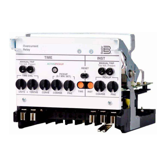
- Page 23 SECTION 2 • CONTROLS AND INDICATORS INTRODUCTION Figure 2-1 illustrates the front panel controls and indicators of the BE1-50/51B-219 and BE1-50/51B-226. Figure 2-2 illustrates the location of switch SW3. Both illustrations have lettered call-outs that correspond to the control and indicator descriptions provided in Table 2-1.
- Page 24 Figure 2-2. Location of SW3 BE1-50/51B-219/-226 Controls and Indicators 9252000981 Rev G...
- Page 25 Table 2-1. BE1-50/51B-219 and BE1-50/51B-226 Controls and Indicators (Refer to Figures 2-1 and 2-2) Locator Control or Indicator Function INST MANUAL TRIP When shorted, the test points (jacks) provide a secure means to Test Points manually trip the controlled breaker. Jacks accept a standard 0.08 inch diameter phone tip plug.
- Page 26 This page intentionally left blank. BE1-50/51B-219/-226 Controls and Indicators 9252000981 Rev G...
-
Page 27: Section 3 • Functional Description
FUNCTIONAL DESCRIPTION ......................3-1 Sensing Input............................3-1 Power Supply ............................. 3-1 Instantaneous Signal.......................... 3-1 Time Signal............................3-1 Microprocessor ........................... 3-1 Power-Off Sensing ..........................3-1 Outputs ............................... 3-2 Figures Figure 3-1. Functional Block Diagram ....................... 3-2 9252000981 Rev G BE1-50/51B-219/-226 Functional Description... - Page 28 This page intentionally left blank. BE1-50/51B-219/-226 Functional Description 9252000981 Rev G...
- Page 29 SECTION 3 • FUNCTIONAL DESCRIPTION GENERAL BE1-50/51B-219 and BE1-50/51B-226 Overcurrent Relays are microprocessor based non-directional relays that measure ac current to provide secure and reliable instantaneous and time overcurrent protection for power systems. FUNCTIONAL DESCRIPTION Sensing Input Single phase ac current from system current transformers (CT) is brought into the Overcurrent Relay at terminals 8 and 9.
- Page 30 The targets will not operate without adequate operating power for the relay. CAUTION Trip circuit voltage is present at the front panel test points. When shorting the test points, use insulated jumpers to avoid contact with these voltages. Figure 3-1. Functional Block Diagram BE1-50/51B-219/-226 Functional Description 9252000981 Rev G...
-
Page 31: Section 4 • Installation
INSTALLATION............................4-1 APPLICATION COORDINATION ......................4-1 CONNECTIONS ............................ 4-3 MAINTENANCE ............................. 4-4 STORAGE.............................. 4-4 Figures Figure 4-1. Coordination Timing Diagram ....................4-2 Figure 4-2. AC Input Connections ......................4-3 Figure 4-3. DC Control Connections ......................4-4 9252000981 Rev G BE1-50/51B-219/-226 Installation... - Page 32 This page intentionally left blank. BE1-50/51B-219/-226 Installation 9252000981 Rev G...
- Page 33 • Close knife-blade switches. • To install the cover, position the interlocking bracket at the top of the new Basler Electric cover into the mating receptacle at the top of the case. Secure the captive fastener at the bottom of the cover.
- Page 34 In Figure 4-1, = 0.209 seconds (relay was at reset). = value < T because rewind has not gone to zero. = value < T because rewind has not gone to zero. Figure 4-1. Coordination Timing Diagram BE1-50/51B-219/-226 Installation 9252000981 Rev G...
- Page 35 15.5 0.161 seconds CONNECTIONS Typical ac input and dc control connections are shown in Figures 4-2 and 4-3. Refer to the block diagram in Section 3 for relay internal connections. Figure 4-2. AC Input Connections 9252000981 Rev G BE1-50/51B-219/-226 Installation...
- Page 36 Figure 4-3. DC Control Connections MAINTENANCE BE1-50/51B-219 and BE1-50/51B-226 overcurrent relays require no preventive maintenance. However, periodic checks should be performed according to scheduled practices. A recommended periodic test is provided in Section 5. If the relay fails to function properly, contact the Technical Sales Support Department of Basler Electric.
-
Page 37: Section 5 • Testing
Test Procedure, Models BE1-50/51B-228 (One Ampere Sensing Input) .......... 5-5 SETTING THE RELAY .......................... 5-7 PERIODIC TESTS ..........................5-7 General............................... 5-7 Periodic Test............................5-7 Figures Figure 5-1. Pickup and Timing Test Setup ....................5-2 Figure 5-2. Target Operational Test Setup....................5-2 9252000981 Rev G BE1-50/51B-219/-226 Testing... - Page 38 This page intentionally left blank. BE1-50/51B-219/-226 Testing 9252000981 Rev G...
-
Page 39: Section 5 • Testing
Output contacts are surge protected. OPERATIONAL TEST PROCEDURE The following procedures verify operation of relays BE1-50/51B-219 (5 ampere model) and BE1-50/51B- 226 (1 ampere model). The test setup of Figures 5-1 and 5-2 are intended primarily as an illustration of the principles involved. - Page 40 Figure 5-1. Pickup and Timing Test Setup TEST SET CURRENT AMPS SOURCE BE1-50/51B-219 TIME INST START STOP TIMER 1.0 Aac INPUT CURRENT LIMITER D2354-20 TARGET CURRENT 12-13-99 Figure 5-2. Target Operational Test Setup BE1-50/51B-219/-226 Testing 9252000981 Rev G...
-
Page 41: Test Procedure, Models Be1-50/51B-218 (Five Ampere Sensing Input)
Insure that SW3 switches are set: SW3-1 for the operating frequency, SW3-2 to OFF, SW3-3 to ON, and SW3-4 ON. • Set TIME DIAL to 4.5. • Set CURVE to S • Set TIME PICKUP to 1.0. • Set INST PICKUP to 90. 9252000981 Rev G BE1-50/51B-219/-226 Testing... - Page 42 Insure that SW3 switches are set: SW3-1 for the operating frequency, SW3-2 to OFF, SW3-3 to ON, and SW3-4 ON. • Set TIME DIAL to 9.9. • Set CURVE to V. • Set TIME PICKUP to 1.0. • Set INST PICKUP to 90. BE1-50/51B-219/-226 Testing 9252000981 Rev G...
-
Page 43: Test Procedure, Models Be1-50/51B-228 (One Ampere Sensing Input)
Insure that SW3 switches are set: SW3-1 for the operating frequency, SW3-2 to OFF, SW3-3 to ON, and SW3-4 ON. • Set TIME DIAL to 4.5. • Set CURVE to S • Set TIME PICKUP to 0.2. • Set INST PICKUP to 18.0. 9252000981 Rev G BE1-50/51B-219/-226 Testing... - Page 44 Insure that SW3 switches are set: SW3-1 for the operating frequency, SW3-2 to OFF, SW3-3 to ON, and SW3-4 ON. • Set TIME DIAL to 4.5. • Set CURVE to I. • Set TIME PICKUP to 0.20. • Set INST PICKUP to 18.0. BE1-50/51B-219/-226 Testing 9252000981 Rev G...
-
Page 45: Setting The Relay
Refer to Section 1 for the instantaneous characteristic curve. Step 5. Verify that the targets operate with one ac ampere of trip current in the trip circuits and that they can be reset using the RESET BUTTON. 9252000981 Rev G BE1-50/51B-219/-226 Testing... - Page 46 This page intentionally left blank. BE1-50/51B-219/-226 Testing 9252000981 Rev G...
- Page 47 Figure A-12. Time Characteristic Curve, I2-Inverse (SW3-3 ON, Similar to GE IAC 51)......A-12 Figure A-13. Time Characteristic Curve, V2-Very Inverse (SW3-3 ON, Similar to GE IAC 53)....A-13 Figure A-14. Time Characteristic Curve, E2-Extremely Inverse (SW3-3 ON, Similar to GE IAC 77) ..A-14 9252000981 Rev G BE1-50/51B-219/-226 Time Characteristic Curves...
- Page 48 This page intentionally left blank. BE1-50/51B-219/-226 Time Characteristic Curves 9252000981 Rev G...
-
Page 49: Appendix A • Time Characteristic Curves
TIME CHARACTERISTIC CURVES Figures A-1 through A-14 illustrate the time characteristic curves that are programmed into the nonvolatile memory of this relay. Figure A-1. Time Characteristic Curve, S-Short Inverse (SW3-3 OFF, Similar to ABB CO-2) 9252000981 Rev G BE1-50/51B-219/-226 Time Characteristic Curves... - Page 50 Figure A-2. Time Characteristic Curve, L-Long Inverse (SW3-3 OFF, Similar to ABB CO-5) BE1-50/51B-219/-226 Time Characteristic Curves 9252000981 Rev G...
- Page 51 Figure A-3. Time Characteristic Curve, D-Definite Time (Similar to ABB CO-6) 9252000981 Rev G BE1-50/51B-219/-226 Time Characteristic Curves...
- Page 52 Figure A-4. Time Characteristic Curve, M-Moderately Inverse (Similar to ABB CO-7) BE1-50/51B-219/-226 Time Characteristic Curves 9252000981 Rev G...
- Page 53 Figure A-5. Time Characteristic Curve, I-Inverse (SW3-3 OFF, Similar to ABB CO-8) 9252000981 Rev G BE1-50/51B-219/-226 Time Characteristic Curves...
- Page 54 Figure A-6. Time Characteristic Curve, V-Very Inverse (SW3-3 OFF, Similar to ABB CO-9) BE1-50/51B-219/-226 Time Characteristic Curves 9252000981 Rev G...
- Page 55 Figure A-7. Time Characteristic Curve, E-Extremely Inverse (SW3-3 OFF, Similar to ABB CO-11) 9252000981 Rev G BE1-50/51B-219/-226 Time Characteristic Curves...
- Page 56 Figure A-8. Time Characteristic Curve, BS142-B (BS142 Very Inverse) BE1-50/51B-219/-226 Time Characteristic Curves 9252000981 Rev G...
- Page 57 Figure A-9. Time Characteristic Curve, BS142-C (BS142 Extremely Inverse) 9252000981 Rev G BE1-50/51B-219/-226 Time Characteristic Curves...
- Page 58 Figure A-10. Time Characteristic Curve, S2-Short Inverse (SW3-3 ON, Similar to GE IAC 55) A-10 BE1-50/51B-219/-226 Time Characteristic Curves 9252000981 Rev G...
- Page 59 Figure A-11. Time Characteristic Curve, L2-Long Inverse (SW3-3 ON, Similar to GE IAC 66) 9252000981 Rev G BE1-50/51B-219/-226 Time Characteristic Curves A-11...
- Page 60 Figure A-12. Time Characteristic Curve, I2-Inverse (SW3-3 ON, Similar to GE IAC 51) A-12 BE1-50/51B-219/-226 Time Characteristic Curves 9252000981 Rev G...
- Page 61 Figure A-13. Time Characteristic Curve, V2-Very Inverse (SW3-3 ON, Similar to GE IAC 53) 9252000981 Rev G BE1-50/51B-219/-226 Time Characteristic Curves A-13...
- Page 62 Figure A-14. Time Characteristic Curve, E2-Extremely Inverse (SW3-3 ON, Similar to GE IAC 77) A-14 BE1-50/51B-219/-226 Time Characteristic Curves 9252000981 Rev G...
- Page 63 ROUTE 143, BOX 269 HIGHLAND, IL 62249 USA http://www.basler.com, info@basler.com PHONE +1 618-654-2341 FAX +1 618-654-2351...
Need help?
Do you have a question about the BE1-50/51B-219 and is the answer not in the manual?
Questions and answers