
Related Manuals for Basler BE1-87T


Summary of Contents for Basler BE1-87T
- Page 1 INSTRUCTION MANUAL TRANSFORMER DIFFERENTIAL RELAY BE1-87T BE1-87T TRANSFORMER DIFFERENTIAL Style No. D2E A1J D1S0F Serial No. XXXXXXXXXXXX PUSH TO ENERGIZE OUTPUT Publication: 9171300990 Revision: R 09/07...
- Page 3 INTRODUCTION This instruction manual provides information about the operation and installation of the BE1-87T Transformer Differential relay. To accomplish this, the following information is provided: • General Information and Specifications • Controls and Indicators • Functional Description • Installation • Test Procedures...
- Page 4 September 2007 CONFIDENTIAL INFORMATION of Basler Electric, Highland Illinois, USA. It is loaned for confidential use, subject to return on request, and with the mutual understanding that it will not be used in any manner detrimental to the interest of Basler Electric.
- Page 5 REVISION HISTORY The following information provides a historical summary of the changes made to the BE1-87T instruction manual (9171300990). Revisions are listed in reverse chronological order. Manual Revision and Date Change • R, 09/07 Replaced magnetic type targets with electronic type targets.
- Page 6 Changed all sections to reflect new Option 1-1. • Added to Section 5 four examples for testing relays to clarify test procedures. • Added to Section 5 one procedure for setting relays. • Corrected typographical and illustration errors. BE1-87T Introduction 9171300990 Rev R...
- Page 7 • Renamed Section 7, Manual Change Information to Section 8, Manual Change Information and added new Section 7, Difference Data to support BE1-87T relays with Sensing Input Type F. • D, 06/92 Manual was revised to include the 1 A, 50 Hz model relay and reformatted to a new Instruction Manual style.
- Page 8 This page intentionally left blank. BE1-87T Introduction 9171300990 Rev R...
-
Page 9: Table Of Contents
30° Internal Phase Shift (Three-Phase Relays ONLY) ..............3-1 Restrained Trip Output ......................... 3-3 Unrestrained Trip Output ......................3-3 Auxiliary Relay Option ........................3-4 Power Supply..........................3-4 Power Supply Status Output (Optional) ..................3-4 Target Indicators (Optional)......................3-4 % of Trip ............................3-5 9171300990 Rev R BE1-87T Introduction... - Page 10 Three-Phase Units........................4-20 SENSING CONNECTION DIAGRAMS .................... 4-20 Single-Phase Input Sensing Connections .................. 4-20 Three-Phase Input Sensing Connections................... 4-20 SETTING THE BE1-87T ........................4-33 Method............................4-33 Procedure One ........................... 4-33 Procedure Two ........................... 4-42 CHECKING THE RELAY SETTINGS AND SYSTEM INPUTS ............4-49 MAINTENANCE ..........................
- Page 11 SETTING NOT 7 ..........................A-7 CT Performance Evaluation: Saturation Error................A-7 Saturation Factor Defined from the ANSI C Classification............A-7 Saturation Factor Defined from the CT Excitation Curve ............. A-8 Saturation Factor Definitions Compared ..................A-8 Conclusion ..........................A-10 9171300990 Rev R BE1-87T Introduction...
- Page 12 This page intentionally left blank. BE1-87T Introduction 9171300990 Rev R...
-
Page 13: Section 1 • General Information
Power transformers can have multiple breakers for a given winding (e.g., ring bus or breaker- and-a-half bus). BE1-87T relays are available with up to five restraint inputs for the single-phase unit and up to three restraint inputs per phase for the three-phase unit. -
Page 14: Application
Additionally, this feature allows sharing the transformer differential relay CTs with other relays or instrumentation. BE1-87T relays use the highest input current (in per unit values) to operate on maximum restraint. The relay does not have a conventional operate winding in the internal magnetics. Operating current is developed within the electronics of the relay. -
Page 15: Fifth-Harmonic Restraint
Magnetizing inrush produces an offset sine wave rich in all harmonics. BE1-87T relays use the second harmonic to restrain operation because it predominates and because it does not occur in significant magnitude or duration at other times. Three-phase BE1-87T relays use second-harmonic sharing. The second-harmonic content of all three phases is summed together to derive the restraint for each phase. -
Page 16: Model And Style Number
Style Number Example The Style Number Identification Chart (Figure 1-1) defines the electrical characteristics and operational features included in BE1-87T relays. For example, if the Style Number were G1E-A1Y-D1S0F, the device would have the following: Model Number (designates the relay as a Basler Electric, Class 100, Transformer Differential... -
Page 17: Specifications
SPECIFICATIONS The BE1-87T relay is available in either single-phase or three-phase configurations and with the following features and capabilities. Current Sensing Inputs The unit is designed to operate from the secondary of current transformers rated at either 1 A or 5 A. Frequency range is ±5 Hz of nominal. -
Page 18: Front Panel Setting
Front panel thumbwheel switches adjust the pickup point of the unrestrained output over a range of 6 to 21 times the tap setting in increments of 1 x Tap. Pickup Accuracy ±3 % of the front panel setting. BE1-87T General Information 9171300990 Rev R... -
Page 19: Outputs
12 dB 5th Harmonic Restraint 12 dB 12 dB 12 dB 12 dB Refer to Figure 1-3 for Unrestrained Response Times and Timing Figure 1-4 for Restrained Response Times. (For 60 Hz units only) 9171300990 Rev R BE1-87T General Information... - Page 20 Figure 1-3. Unrestrained Response Times Figure 1-4. Restrained Response Times BE1-87T General Information 9171300990 Rev R...
-
Page 21: Isolation
In standard tests, the relay has withstood 2 g in each of three mutually perpendicular axes swept over the range of 10 to 500 Hz for a total of six sweeps, 15 minutes each sweep, without structural damage or degradation of performance. 9171300990 Rev R BE1-87T General Information... -
Page 22: Operating Temperature
22.3 lbs (10.1 kg) maximum (three-phase unit) Weight 19.5 lbs (8.85 kg) maximum (single-phase unit) All units are supplied in an M1 case size. See Section 4, Case Size Installation for case dimensions. 1-10 BE1-87T General Information 9171300990 Rev R... -
Page 23: Section 2 • Controls And Indicators
SECTION 2 • CONTROLS AND INDICATORS LOCATION OF CONTROLS AND INDICATORS Table 2-1 lists and briefly describes the operator controls and indicators of the BE1-87T Transformer Differential Relay. Reference the call-out letters A through M to Figures 2-1 to 2-3; N through Q to Figure 2-5. - Page 24 Red LED lights when the % OF TRIP pushbutton P is pressed and the restraint current is below the slope characteristic kneepoint as defined in Table 1-1. That is, the relay will operate at minimum pickup (0.35 times tap). BE1-87T Controls and Indicators 9171300990 Rev R...
- Page 25 4 LEDs: 20% (Red LED) 5 LEDs: 40% (Red LED) 6 LEDs: 60% (Red LED) 7 LEDs: 80% (Red LED) 8 LEDs: 100% (Red LED) A bar chart above the LEDs shows the relative percentage of trip. 9171300990 Rev R BE1-87T Controls and Indicators...
- Page 26 Style No. G4E A1J D0S0F Serial No. XXXXXXXXXXXX PUSH TO ENERGIZE OUTPUT See Fig. 2-4 ELEMENT FUNCTION U.S. PATENT 5,014,153 PATENTED IN CANADA, 1993 Figure 2-1. Sensing Input Range 1 or 3 Three-Phase, Three Inputs BE1-87T Controls and Indicators 9171300990 Rev R...
- Page 27 Style No. D4E A1J D0S5F Serial No. XXXXXXXXXXXX PUSH TO ENERGIZE OUTPUT See Fig. 2-4 FUNCTION U.S. PATENT 5,014,153 PATENTED IN CANADA, 1993 Figure 2-2. Sensing Input Range 1 or 3, Single-Phase, Five Inputs 9171300990 Rev R BE1-87T Controls and Indicators...
- Page 28 Style No. E2E A1J D0S0F Serial No. XXXXXXXXXXXX PUSH TO ENERGIZE OUTPUT See Fig. 2-4 ELEMENT FUNCTION U.S. PATENT 5,014,153 PATENTED IN CANADA, 1993 Figure 2-3. Sensing Input Range 2 or 4 Three-Phase, Two Inputs BE1-87T Controls and Indicators 9171300990 Rev R...
- Page 29 Δ 1 Δ 2 Δ 1 Δ 2 Δ 1 Δ 2 UNRES SECTION OF THE (VERTICAL) MOTHER BOARD AT LEFT REAR OF RELAY CR19 AUX RES Figure 2-4. Controls Mounted Inside the Relay 9171300990 Rev R BE1-87T Controls and Indicators...
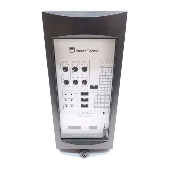
- Page 30 BE1-87T TRANSFORMER DIFFERENTIAL Style No. D3E A1J D1S0F Serial No. XXXXXXXXXXXX PUSH TO ENERGIZE OUTPUT Figure 2-5. Sensing Input Range 2 or 4, Option 1-1, Single-Phase, Five Inputs, % OF TRIP Option BE1-87T Controls and Indicators 9171300990 Rev R...
-
Page 31: Section 3 • Functional Description
DESCRIPTION The functional block diagrams of Figures 3-1 and 3-2 illustrate the overall operation of the BE1-87T Transformer Differential Relay. (Figure 3-1 shows Phase A or single-phase functions; Figure 3-2 shows the additional functions for phases B and C.) Since the three phases are functionally similar, only phase A is shown in detail in Figure 3-1. - Page 32 C SAME AS IN. 2 IN. 3 TARGET UNRESTRAINED COM. OPTIONAL RESTRAINED CONTACTS FOR EACH OF 3 PHASES (SEE NOTE 5 BE1-87T D741-001b 7-11-94 Figure 3-2. Functional Block Diagram, Phase B and Phase C BE1-87T Functional Description 9171300990 Rev R...
-
Page 33: Restrained Trip Output
UNRESTRAINED PICKUP LEVEL switch is shown in Figures 2-1 through 2-5. When this reference is exceeded, the Unrestrained Trip output relay is energized. An unrestrained trip is not affected by through-current or harmonic inhibits. 9171300990 Rev R BE1-87T Functional Description... -
Page 34: Auxiliary Relay Option
(terminals 19 and 20) so that the Power Supply Status output terminals can provide a remote indication that the BE1-87T has been withdrawn from its case or that it has been taken out of service by removing the connection plugs. -
Page 35: Of Trip
NOTE Prior to September 2007, the BE1-87T target indicators consisted of magnetically latched, disc indicators. These mechanically latched target indicators have been replaced by the electronically latched LED targets in use today. % of Trip When the % of trip pushbutton Q is pushed, eight LEDs, shown in Figure 2-5, are used to indicate the percentage of operating current to: Minimum pickup (LED M also lights);... - Page 36 This page intentionally left blank. BE1-87T Functional Description 9171300990 Rev R...
-
Page 37: Section 4 • Installation
MOUNTING Because the BE1-87T, Transformer Differential Relay, is of solid-state design. It does not have to be mounted vertically. Any convenient mounting angle may be chosen. The BE1-87T relay is supplied in a standard M1 size drawout case and can be either semi-flush or projection mounted (Option 4). - Page 38 Inches (Millimeters) Figure 4-1. Outline Dimensions, Front View BE1-87T Installation 9171300990 Rev R...
- Page 39 Inches (Millimeters) Figure 4-2. Outline Dimensions, Rear View 9171300990 Rev R BE1-87T Installation...
- Page 40 Inches (Millimeters) Figure 4-3. Outline Dimensions, Side View (Semi-Flush Mounting) BE1-87T Installation 9171300990 Rev R...
- Page 41 Inches (Millimeters) Figure 4-4. Panel Drilling Diagram (Semi-Flush Mounting) 9171300990 Rev R BE1-87T Installation...
- Page 42 Inches (Millimeters) Figure 4-5. Outline Dimensions, Side View (Projection Mounting) BE1-87T Installation 9171300990 Rev R...
- Page 43 OPTIONAL RECTANGULAR CUTOUT MAY REPLACE 10 DRILLED HOLES. TERMINAL NUMBERS SHOWN ARE AS VIEWED FROM REAR OF RELAY. BOTTOM HALF OF PANEL DRILLING DIAGRAM (FROM CENTERLINE DOWN) IS SHOWN IN FIGURE 4-6b. Inches (Millimeters) Figure 4-6a. Panel Drilling Diagram-Top Half (Projection Mounting) 9171300990 Rev R BE1-87T Installation...
- Page 44 Inches (Millimeters) Figure 4-6b. Panel Drilling Diagram-Bottom Half (Projection Mounting) BE1-87T Installation 9171300990 Rev R...
-
Page 45: Dielectric Test
Except as noted above, connections should be made with a minimum wire size of 14 AWG. Figures 4-7 through 4-10 show case terminals designations for four typical relay configurations. Figures 4-11 through 4-14 show the internal connections of the BE1-87T. Control circuit connections are shown in Figures 4-15 through 4-18. - Page 46 CONFIGURATION IS DEPENDENT ON STYLE SELECTED. Figure 4-8. Case Terminals: Three-Phase, Two Input (Sensing Input Type E), Output Option E Figure 4-9. Case Terminals: Three-Phase, Two Input (Sensing Input Type E), Output Option F 4-10 BE1-87T Installation 9171300990 Rev R...
- Page 47 Figure 4-10. Case Terminals: Three-Phase, Three Input (Sensing Input Type G), Output Option E 9171300990 Rev R BE1-87T Installation 4-11...
- Page 48 Figure 4-11. Internal Connections: Single-Phase, Five Input (Sensing Input Type D), Output Option E 4-12 BE1-87T Installation 9171300990 Rev R...
- Page 49 Figure 4-12. Internal Connections: Three-Phase, Two Input (Sensing Input Type E), Output Option E 9171300990 Rev R BE1-87T Installation 4-13...
- Page 50 REST REST TARGET POWER TRIP TRIP SUPPL Y UNREST . REST TRIP TRIP REST BE1-87T UNREST D983-025 REST REST 2-18-93 Figure 4-13. Internal Connections: Three-Phase, Two Input (Sensing Input Type E), Output Option F 4-14 BE1-87T Installation 9171300990 Rev R...
- Page 51 (OPTIONAL) RESTRAINED UNREST LEGEND: 87T TRANSFORMER DIFFERENTIAL RELAY LOCKOUT RELAY POWER OPTIONAL CURRENT-OPERATED TARGETS AUXILIARY OUTPUT OPTION FOR SINGLE-PHASE: NO, NC, OR SPDT BE1-87T D240-008 4-21-94 Figure 4-15. Control Circuits: Single-Phase, Output Option E 9171300990 Rev R BE1-87T Installation 4-15...
- Page 52 PHASE C PHASE A PHASE B LEGEND: 87T TRANSFORMER POWER DIFFERENTIAL RELAY BE1-87T LOCKOUT RELAY D329-004 3-7-91 OPTIONAL CURRENT- OPERATED TARGETS Figure 4-17. Control Circuits: Three-Phase, Two Input (Sensing Input E), Output Option F 4-16 BE1-87T Installation 9171300990 Rev R...
-
Page 53: Relay Disassembly
CAUTION 1. Always remove power from the BE1-87T by removing the connection plugs before removing or installing a printed circuit board. 2. Always neutralize static body charge before placing a printed circuit board on—or removing one from—metal surfaces. -
Page 54: Disabling Unused Inputs
Analog #1 Board, shown in Figure 4-19. To avoid personal injury or equipment damage, do NOT proceed unless thoroughly familiar with the instructions in sections RELAY OPERATING PRECAUTIONS RELAY DISASSEMBLY: Precautions. 4-18 BE1-87T Installation 9171300990 Rev R... - Page 55 DISABLE INPUT 4 J2 & J5 ENABLE INPUT 4 J2 & J5 -12V FACTORY NOT FIELD ADJUSTMENT AGND ADJUSTABLE TP11 TP10 R163 BE1-87T D1924-12 9-21-94 R177 Figure 4-21. Unused Input-Disabling Jumpers, Analog #1 Board: Option 1-1 9171300990 Rev R BE1-87T Installation 4-19...
-
Page 56: Single-Phase Units
Typical single-phase input sensing connections are illustrated in Figure 4-22. Single-phase units may also be used in three-phase configurations, one on each phase. Figure 4-23 through Figure 4-26 show several typical three-phase sensing examples using three BE1-87T single- phase relays. Many other configurations are possible. - Page 57 BREAKER BREAKER INPUT 5 OPTIONAL INPUT 4 INPUTS INPUT 3 INPUT 2 INPUT Figure 4-22. Typical Single-Phase Sensing Connections SWITCH BOARD TERMINAL BLOCKS BE1-87T-1 BE1-87T-2 BE1-87T-3 D1186-02 03-12-98 Figure 4-23. Single-Phase Connections, Delta-Wye Configuration 9171300990 Rev R BE1-87T Installation 4-21...
- Page 58 SWITCH BOARD TERMINAL BLOCKS BE1-87T-1 BE1-87T-2 BE1-87T-3 D1186-20.vsd 04-16-99 Figure 4-24. Single-Phase Connections, Wye-Wye Configuration 4-22 BE1-87T Installation 9171300990 Rev R...
- Page 59 SWICH BOARD TERMINAL BLOCKS BE1-87T-1 (1) 11 BE1-87T-2 (1) 11 BE1-87T-3 (1) 11 D1186-03 03-12-98 Figure 4-25. Single-Phase Connections, Delta-Delta-Wye Configuration 9171300990 Rev R BE1-87T Installation 4-23...
-
Page 60: Three-Phase Input Sensing Connections
1. By connecting the system CTs to complement the power transformer connections (i.e., a wye/delta CT can negate the phase shift of a delta/wye power transformer, and vice versa). 2. By utilizing the internal 30° Phase Shift Compensation that is a feature of three-phase BE1-87T relays. - Page 61 The internal compensation can apply to any power transformer with any combination of wye, delta or autotransformer winding connections. A procedure to check the differential balance is described later in this section, CHECKING THE RELAY SETTINGS AND SYSTEM INPUTS. 9171300990 Rev R BE1-87T Installation 4-25...
- Page 62 Figure 4-28a by connecting the wye side CTs in delta such that the currents sent to the relay are A-B, B-C and C-A. This is shown in Figure 4-28b by selecting phase compensation jumper position Δ2 for the wye side input. 4-26 BE1-87T Installation 9171300990 Rev R...
- Page 63 18. Figure 4-28a. Three-Phase Connections, Delta-Wye Configuration, CT Compensation Switch BE1-87T board terminal Δ2 blocks D2751-22 02-05-98 Phase shift jumper position on analog board #2. Figure 4-28b. Three-Phase Connections, Delta-Wye Configuration, Internal Phase Compensation 9171300990 Rev R BE1-87T Installation 4-27...
- Page 64 A-C, B-A and C-B to compensate. This is shown in Figure 4-27 by selecting phase compensation jumper position Δ1 for the wye side input. 4-28 BE1-87T Installation 9171300990 Rev R...
- Page 65 BE1-87T Switch board terminal blocks D2751-24 03-12-98 Phase shift jumper position on analog board #2. Figure 4-30. Three-Phase Connections, Delta-Delta Configuration 9171300990 Rev R BE1-87T Installation 4-29...
- Page 66 Delta compensate the currents to block zero sequence currents being supplied by the transformer bank. This is shown in Figure 4-31a by connecting the CTs in Delta. In Figure 31b, compensation is shown by internal phase compensation jumper setting. 4-30 BE1-87T Installation 9171300990 Rev R...
- Page 67 D2751-26 Phase shift jumper 03-12-98 position on analog board #2. NOTES: *THE BE1-87T MUST USE THE SAME PHASE COMPENSATION JUMPER POSITION ON ALL INPUTS. Figure 4-31b. Three-Phase Connections, Wye-Wye or Autotransformer Configuration, Internal Phase Compensation 9171300990 Rev R BE1-87T Installation...
- Page 68 Figure 4-32 by selecting phase compensation jumper position Δ2 for these inputs. This also provides zero sequence blocking for these inputs since this transformer configuration is a source of zero sequence currents. 4-32 BE1-87T Installation 9171300990 Rev R...
-
Page 69: Setting The Be1-87T
Both procedures determine: 1. The matching tap and slope settings required to implement the restrained function, and 2. The unrestrained pickup setting as a multiple of the BE1-87T tap setting (i.e., the INPUT switches). The matching tap procedure is conventional, providing tap values proportional to the normal currents as seen by the relay. - Page 70 The CT burden voltage with I flowing Base accuracy class CT voltage rating Accuracy class CT effective voltage where not all turns are used, which equals Unrestrained pickup setting, in multiples of tap (6 to 21) x TAP 4-34 BE1-87T Installation 9171300990 Rev R...
- Page 71 One-Way Lead Burden (ohms) CT Connection (Three-Phase) NOTE Three-phase is the most common application of the BE1-87T. Using single-phase relays requires a Delta connection for the High side and Low side CTs (I to match the tertiary connection in the example detailed in Figure 4-32).
- Page 72 Determine the Desired Tap (T TERTIARY 18.22 7.55 6.04 6.04 6.03 2.50 Step 9. Select taps by rounding T to the nearest tenth: HIGH TERTIARY T = 2.0 T = 6.0 T = 2.5 4-36 BE1-87T Installation 9171300990 Rev R...
- Page 73 For delta-connected CTs, based on a three-phase fault (refer to Appendix A, Setting Note 2): Where: = determined in Step 12 = relay resistance in ohms (< 0.05 ohm) = winding burden = one-way lead resistance in ohms 9171300990 Rev R BE1-87T Installation 4-37...
- Page 74 (Base Accuracy) (Number of CT Turns in Use) Maximum Ratio HIGH TERTIARY 3000 1200 3000 2000 Step 16. Determine the saturation factor (S Note: V is the largest burden voltage from steps 13 and 14. HIGH TERTIARY 4-38 BE1-87T Installation 9171300990 Rev R...
- Page 75 Step 19. Using the results of Step 18, set the UNRESTRAINED PICKUP LEVEL control. Referring to the table on the BE1-87T front panel, select the tap position (X TAP) that is higher than the result obtained in Step 18. Therefore, for this example, select SET position P (=19 X TAP) which is higher than the above result of 18.2 A.
- Page 76 The recommended restrained slope setting (S) is a function of the total mismatch and the power transformer exciting current. This provides an ample security margin with respect to the characteristic kneepoint of the BE1-87T. Refer to Figure 4-34. I op...
- Page 77 Current Rating of Power Recommended Minimum Mismatch in % Transformer in RESTRAINED PICKUP Multiples of TAP (I LEVEL Setting* (Slope) 12.5 If S >0.5, set the RESTRAINED PICKUP LEVEL setting (slope) to S =60%. 9171300990 Rev R BE1-87T Installation 4-41...
-
Page 78: Procedure Two
Determine the full load primary current (I ) of each winding: × MVA ratingof transformer 1,000 I P = LINE - LINE Use the top kVA rating of the transformer when making the calculations: HIGH 20,000 20,000 167.35 . 98 4-42 BE1-87T Installation 9171300990 Rev R... - Page 79 Step 5. Determine the spread ratio of the relay currents (largest/smallest) which must be less than the 4.45 capability of the BE1-87T: Spread = 10.02/2.79 = 3.59 If the spread exceeds 4.45, consider changing CT ratios or use auxiliary CTs.
- Page 80 (based on the power transformer in the neutral tap ± position) to the total permissible tap excursion from neutral. In this example, a 10 % load-tap change (LTC) must be accommodated. Therefore: =0.22 + 10 = 10.22% 4-44 BE1-87T Installation 9171300990 Rev R...
- Page 81 • For delta-connected CTs: is a function of the proportion of positive-sequence to zero-sequence currents but may be approximated by the same equation (for worst case). 9171300990 Rev R BE1-87T Installation 4-45...
- Page 82 Instantaneous (Unrestraint) Unit Setting Step 17. Determine the maximum external fault multiple (I • For wye-connected CTs and with WYE jumpers on Analog Board #2, shown in Figure 2- Maximum Relay Fault Current Corresponding Tap 4-46 BE1-87T Installation 9171300990 Rev R...
- Page 83 Step 19. Using the results of Step 18, set the UNRESTRAINED PICKUP LEVEL control. Referring to the table on the BE1-87T front panel, select the tap position (X TAP) that is higher than the result obtained in Step 18. Therefore, for this example, select SET position G (=12 X TAP) which is higher than the above result of 11.17 X TAP.
- Page 84 The recommended restrained slope setting (S) is a function of the total mismatch and the power transformer exciting current. This provides an ample security margin with respect to the characteristic kneepoint of the BE1-87T. Refer to Figure 4-34. Specifically, if the maximum saturation factor S (from Step 16) exceeds 0.5, set the...
-
Page 85: Checking The Relay Settings And System Inputs
If the REST. TRIP or UNREST. TRIP LEDs light, recheck the system current inputs and relay settings. If actual waveforms, as sensed by the BE1-87T are desired, a procedure using a circuit board Extender Card shown in Figure 5-1 and an oscilloscope is available. -
Page 86: Maintenance
30 minutes. TEST PLUG Test plugs (Basler p/n 10095) provide a quick, easy method of testing relays without removing them from their case. Test plugs are simply substituted for the connection plugs. This provides access to the external stud connections as well as to the internal circuitry. - Page 87 1 through 10 facing up. When using the test plug in the upper part of the relay, the numbers 11 through 20 are face up. It is impossible, due to the construction of the test plug, to insert it with the wrong orientation. 9171300990 Rev R BE1-87T Installation 4-51...
- Page 88 This page intentionally left blank. 4-52 BE1-87T Installation 9171300990 Rev R...
-
Page 89: Section 5 • Test Procedures
Tests provided in this section be performed. These comprehensive tests verify all operating parameters including calibration. BE1-87T relay Verification Tests are divided into two groups based on the current CT ampere rating and the nominal operating frequency: (See the first position of the Style Number and the Sensing Input Range Option as shown in Figure 1-1.) -
Page 90: Restrained Pickup Testing Examples
⎜ ⎟ ⎜ ⎟ ⎝ ⎠ ⎝ ⎠ This means the pu restraint current is to the right of the intersection of the slope characteristic with the 0.35 MPU horizontal line (see Figure 1-2). BE1-87T Test Procedures 9171300990 Rev R... - Page 91 1 - 0.15 < 1.983 Therefore: Use Equation 2 or 2a. From Figure 1-2 (the percentage restraint characteristic of the BE1-87T at 15% slope), the minimum current where trip occurs is: = 1 pu + 0.35 trip = 1.35 pu...
- Page 92 0.15 1 - (0.15) > 1.983 Therefore: Use Equation 1 or 1a. From Figure 1-2 (the percentage restraint characteristic of the BE1-87T at 15% slope), the minimum current where trip occurs is: 3 pu I trip 3.53 pu In terms of current, the trip current is: I trip 3.53 pu...
-
Page 93: Decreasing One Input From Balance
⎞ (Equation 4a) − ⎜ ⎟ 0 35 trip ⎝ ⎠ Example Three: Assume: tap = 2, tap = 3.8, slope = 15%. Inputs: = 2 A (1 pu) = 3.8 A (1 pu) 9171300990 Rev R BE1-87T Test Procedures... - Page 94 1 < > 0.15 < 2.333 Therefore: Use Equation 4 or 4a. From Figure 1-2 (the percentage restraint characteristic of the BE1-87T at 15% slope), the minimum current where trip occurs is: I trip 1 pu - 0.35 = 0.65 pu...
-
Page 95: Test Setup Diagrams
Figure 1-2. TEST SETUP DIAGRAMS Refer to the appropriate test setup diagram under “Related Topics.” Figure 5-2. Test Setup: Single-Phase Figure 5-3. Test Setup: Three-Phase, Sensing Input Type E, Output Option E 9171300990 Rev R BE1-87T Test Procedures... - Page 96 Figure 5-4. Test Setup: Three-Phase, Sensing Input Type E, Output Option F Figure 5-5. Test Setup: Three-Phase, Sensing Input Type G, Output Option E BE1-87T Test Procedures 9171300990 Rev R...
-
Page 97: Verification Tests: 5 Amp Ct, 50 Or 60 Hz Units
VERIFICATION TESTS: 5 AMP CT, 50 OR 60 HZ UNITS CAUTION Current supplied to the BE1-87T input terminals must not exceed 20 A continuous or 250 A for 1 second. Whenever 20 A must be exceeded, provisions must be made to cut off the sensing current automatically after a suitable time interval. -
Page 98: Input (Or Tap) Switch Verification
Set the input under test to the 3.9 tap position as shown in Table 5-2. Set the RESTRAINED PICKUP LEVEL switch to position A (15%). Apply current to the input under test, increasing 5-10 BE1-87T Test Procedures 9171300990 Rev R... -
Page 99: Unrestrained Pickup Verification
Set the INPUT 1 (tap) switches to the 2.0 A position. Connect the relay as appropriate (refer to Figures 5-2 through 5-5) using terminals 11 & 13 (Input 1 for both single-phase and three- phase units). 9171300990 Rev R BE1-87T Test Procedures 5-11... -
Page 100: Fifth-Harmonic Restraint Verification
35.0 ±3% for both single-phase and three-phase units. Step 5. Three-Phase Units Only: Repeat Steps 1 through 4 for phase B (terminals 12 & 13) and phase C (terminals 14 & 13). 5-12 BE1-87T Test Procedures 9171300990 Rev R... -
Page 101: Response Time Verification
Restrained Trip 10 x Pickup 73 ms 67 ms 37 ms Unrestrained Trip 2 x Pickup 70 ms 57 ms 57 ms Unrestrained Trip 10 x Pickup 32 ms 28 ms 10 ms 9171300990 Rev R BE1-87T Test Procedures 5-13... -
Page 102: Verification Tests: 1 Amp Ct, 50 Or 60 Hz Units
VERIFICATION TESTS: 1 AMP CT, 50 OR 60 HZ UNITS CAUTION Current supplied to the BE1-87T input terminals must not exceed 4 A continuous or 50 A for 1 second. Whenever 4 A must be exceeded, provisions must be made to cut off the sensing current automatically after a suitable time interval. -
Page 103: Input (Or Tap) Switch Verification
PICKUP LEVEL switch to position A (15%). Apply current to the input under test, increasing the current until the REST. TRIP LED lights. At this point, the input current should be 0.273 A ± ± 20 mA. 9171300990 Rev R BE1-87T Test Procedures 5-15... -
Page 104: Unrestrained Pickup Verification
Three-Phase Units Only: Set the Calibrate toggle switch S2 (letter D of Figure 2-4) to the CAL Step 2. position on each of the three Analog #1 boards. These three toggle switches are readily 5-16 BE1-87T Test Procedures 9171300990 Rev R... -
Page 105: Fifth-Harmonic Restraint Verification
35.0 ±3% for both single-phase and three-phase styles. Step 5. Three-Phase Units Only: Repeat Steps 1 through 4 for phase B (terminals 12 & 13) and phase C (terminals 14 & 13). 9171300990 Rev R BE1-87T Test Procedures 5-17... -
Page 106: Response Time Verification
Restrained Trip 10 x Pickup 73 ms 67 ms 37 ms Unrestrained Trip 2 x Pickup 64 ms 52 ms 57 ms Unrestrained Trip 10 x Pickup 32 ms 28 ms 10 ms 5-18 BE1-87T Test Procedures 9171300990 Rev R... -
Page 107: Operational Test Procedures
Relay Disassembly and the procedures listed in the RESTRAINED PICKUP TESTING EXAMPLES at the beginning of this section. These tests may be performed by removing the BE1-87T to a test station or with the relay installed. CAUTION If testing an installed relay, be sure to isolate the current inputs and the relay outputs from the system. -
Page 108: Fifth-Harmonic Inhibit
Does not verify that the jumpers have been properly set. It is possible to completely test the BE1-87T with the jumpers set to the in-service position and still use only two input current sources. When the jumpers are in the positions shown in Table 5-9, the respective current inputs are compared. -
Page 109: Jumper Positions Wye-Wye
Verification Tests: 5 Amp CT or Verification Tests: 1 Amp CT in this section. The C- phase differential circuit sees no current and does not respond. Step 2. Connect Input 1 current to terminals A and C. Connect Input 2 current to terminals N and C. 9171300990 Rev R BE1-87T Test Procedures 5-21... - Page 110 Verification Tests: 5 Amp CT or Verification Tests: 1 Amp CT in this section. The A- phase differential circuit sees no current and does not respond. Step 3. Connect Input 1 current to terminals C and N. Connect Input 2 current to terminals C and N. 5-22 BE1-87T Test Procedures 9171300990 Rev R...
- Page 111 Verification Tests: 5 Amp CT or Verification Tests: 1 Amp CT in this section. The B- phase differential circuit sees no current and does not respond. Step 3. Connect Input 1 current to terminals B and N. Connect Input 2 current to terminals N and C. 9171300990 Rev R BE1-87T Test Procedures 5-23...
- Page 112 This verifies the B- and C-phase differential circuits which respond together as provided earlier in the Verification Tests: 5 Amp CT or Verification Tests: 1 Amp CT in this section. The A- phase differential circuit sees no current and does not respond. 5-24 BE1-87T Test Procedures 9171300990 Rev R...
-
Page 113: Section 6 • Difference Data
This procedure prevents false trips. During installation, the lower connection plug should be installed last. DIFFERENCES Revision P to BE1-87T relays made sensing input type F obsolete and created sensing input type G, for three-phase, three inputs for each phase. Primary differences between sensing input types F and G are: •... - Page 114 Figure 6-1. Style Number Identification Chart BE1-87T Difference Data 9171300990 Rev R...
- Page 115 Figure 6-2. Typical Internal Connections, Three-Phase, Sensing Input Type F, Output Option E 9171300990 Rev R BE1-87T Difference Data...
- Page 116 Figure 6-3. Case Terminals, Sensing Input Type F, Output Option E Figure 6-4. Test Setup, Sensing Input Type F, Output Option E BE1-87T Difference Data 9171300990 Rev R...
-
Page 117: Appendix A • Setting Notes
(i.e. taps) in proportion to their voltage rating. It does not mean that the windings will necessarily carry the maximum rating. D2751-16 01-30-98 V I V I × × S = Winding Rating (MVA) Figure A-1. Multi-winding Transformer 9171300990 Rev R BE1-87T Setting Notes... -
Page 118: Setting Note 2
SETTING NOTE 2 D2751-17 01-30-98 =-(I )-(I )-(I Since I =-(I Where: = 3-Phase fault current = Relay burden = Lead burden = Winding burden Figure A-2. CT Burden-Delta Connected CTs 3-Phase Fault BE1-87T Setting Notes 9171300990 Rev R... -
Page 119: Setting Note 3
Phase 2 carries twice the fault current returning from the relay to the CTs. Therefore, the maximum current φφ × ⎛ ⎞ ⎜ ⎟ × φ ⎜ ⎟ ⎝ ⎠ × φ Figure A-3. Phase-Phase Fault Delta Connected CTs 9171300990 Rev R BE1-87T Setting Notes... -
Page 120: Setting Note 4
) can be evaluated with this equation. The following plots show the calculated slope and the resulting margin for M varying from 1 to 11% and I varying from .5 to 10 × I 2 (plot shows BE1-87T Setting Notes 9171300990 Rev R... - Page 121 D2751-28 02-12-98 Figure A-5. BE1-87T Slope vs. M and I D2751-29 02-12-98 Figure A-6. BE1-87T Margin vs. M and I 9171300990 Rev R BE1-87T Setting Notes...
-
Page 122: Setting Note 6
For this worst case example, the maximum inrush current is below the UR threshold. For significant source impedance values, we assume that the inrush current will decrease in proportion to the decrease in the fault current and thus maintain security with the recommended settings. BE1-87T Setting Notes 9171300990 Rev R... -
Page 123: Setting Not 7
Figure 2). We can define a measure of the degree of saturation with the saturation factor (SF): SF = By examination of triangles OAB and OCD, the same saturation factor can be expressed as: SF = 9171300990 Rev R BE1-87T Setting Notes... -
Page 124: Saturation Factor Defined From The Ct Excitation Curve
Using the equivalent circuit in Figure 1 and the ANSI Accuracy Class definition that the CT must be able to source 20 times nominal current into a standard burden Zc, we now develop a comparative analysis between the two definitions: SF = SF = BE1-87T Setting Notes 9171300990 Rev R... - Page 125 The absolute values of SF and SF` are compared in Figure 4 for the particular case where Zc=2, ZB=0.5 and Rs=0.8 when IF varies from 0 to 100A. SF and SF` for Zc=2, ZB=0.5, Rs=0.2 Figure 4. Comparing SF and SF` 9171300990 Rev R BE1-87T Setting Notes...
-
Page 126: Conclusion
This analysis shows that the easy to apply SF based on the ANSI Accuracy Class may yield optimistic results in cases where the CT internal resistance is significant. The Excitation curve method, requiring more data, yields more accurate results and should be used when the SF is marginal. A-10 BE1-87T Setting Notes 9171300990 Rev R... - Page 127 ROUTE 143, BOX 269 HIGHLAND, IL 62249 USA http://www.basler.com, info@basler.com PHONE +1 618-654-2341 FAX +1 618-654-2351...
Need help?
Do you have a question about the BE1-87T and is the answer not in the manual?
Questions and answers