Table of Contents
Advertisement
Quick Links
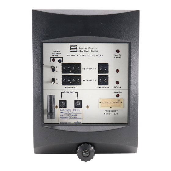
INSTRUCTION MANUAL
DIGITAL FREQUENCY RELAY
U N D E R
V O L T A G E
INHIBIT
O
U
O
U
1
FOR
BE1-81O/U
Basler Electric
Highland, Illinois
R
SOLID-STATE PROTECTIVE RELAY
-
-
-
-
5
8
5
0
SETPOINT 1
+
+
+
+
-
-
-
-
5
8
5
0
SETPOINT 2
+
+
+
+
F R E Q U E N C Y
S E T P O I N T
2
T 3 E E 1 J B 7 S O F
F R E Q U E N C Y
BE1-81 O/U
Publication Number: 9 1373 00 990
O U T O F
R A N G E
-
-
1
0
+
+
P I C K U P
-
-
1
0
+
+
P I C K U P
TIME DELAY
P O W E R
D 1 2 7 8 - 0 9
03-23-98
Revision: G
06/99
Advertisement
Table of Contents

Subscribe to Our Youtube Channel
Related Manuals for Basler BE1-81O/U


Summary of Contents for Basler BE1-81O/U
- Page 1 INSTRUCTION MANUAL DIGITAL FREQUENCY RELAY BE1-81O/U Basler Electric U N D E R Highland, Illinois V O L T A G E INHIBIT SOLID-STATE PROTECTIVE RELAY O U T O F R A N G E SETPOINT 1 P I C K U P...
- Page 2 INTRODUCTION This Instruction Manual provides information concerning the operation and installation of BE1-81O/U Digital Frequency Relays. Unit Revision E and M to the relay incorporated design changes that are backward compatible with previous versions of the relay. To accomplish this, the following is provided.
- Page 3 The availability and design of all features and options are subject to modification without notice. Should further information be required, contact Basler Electric Company, Highland, Illinois. BASLER ELECTRIC ROUTE 143, BOX 269 HIGHLAND, IL 62249 USA http://www.basler.com, info@basler.com...
-
Page 4: Table Of Contents
Definite TIME DELAY (Option E1) ......5-3 Definite TIME DELAY (Option E2) ......5-3 BE1-81O/U - Introduction... - Page 5 Bandpass Filter Characteristics ......3-1 Figure 3-2. BE1-81O/U Functional Block Diagram ......3-2 Figure 3-3.
-
Page 6: Section 1 • General Information
(Basler part number 9 1655 00 100) to test or troubleshoot. An available test plug (Basler part number 10095 or G.E. part number 12XLA12A1) enables the relay to be tested in place without distributing external control circuit wiring. -
Page 7: Model And Style Number
The model number BE1-81 O/U designates the relay as a Basler electric, Class 100, Digital Frequency Relay. -
Page 8: Specifications
(operated by a minimum of 0.2 A through the output trip circuit). When the target is current operated, the trip output circuit current must be limited to 30 A for 1 second, 7 A for 2 minutes, and 3 A continuously. BE1-81O/U - General Information... -
Page 9: Undervoltage Inhibit
Maintains proper operation when tested for interference in accordance with IEC C37.90-1989, Trial-Use Standard Withstand Capability of Relay Systems to Radiated Electromagnetic Interference from Transceivers. Surge Withstand Capability Qualified to ANSI/IEEE C37.90.1-1989 Standard Surge Withstand BE1-81O/U - General Information... - Page 10 -40 C (-40 F) to 85 C (185 F) Storage Range Weight Approximately 18 pounds (M1 case) or 13 pounds (S1 case) net. Case Size M1 (three or four setpoints) or S1 (one or two setpoints). BE1-81O/U - General Information...
-
Page 11: Figure 1-2. Inverse Time Overfrequency Characteristic Curves
Figure 1-2. Inverse Time Overfrequency Characteristic Curves BE1-81O/U - General Information... -
Page 12: Figure 1-3. Inverse Time Underfrequency Characteristic Curves
Figure 1-3. Inverse Time Underfrequency Characteristic Curves BE1-81O/U - General Information... -
Page 13: Section 2 Human Machine Interface (Controls And Indicators)
SECTION 2 • HUMAN MACHINE INTERFACE (Controls And Indicators) DESCRIPTION Table 2-1 lists and briefly describes the operator controls and indicators of the BE1-81O/U Digital Frequency Relay. Reference the call-out letters to Figures 2-1, 2-2, and 2-3. Table 2-1. BE1-81 O/U Controls and Indicators... -
Page 14: Figure 2-1. Location Of Controls And Indicators
SETPOINT T 3 E E 1 J B 7 S O F F R E Q U E N C Y BE1-81 O/U D1185-07 03-17-98 Figure 2-1. Location of Controls and Indicators BE1-81O/U - Human Machine Interface (Controls And Indicators) -
Page 15: Figure 2-2. Location Of Controls And Indicators, S1 Case
Section 3 is also marked on the switch; S and C are marked on the circuit board. Figure 2-2. Location of Controls and Indicators S1 Case (Relays Revision C and Previous) BE1-81O/U - Human Machine Interface (Controls And Indicators) -
Page 16: Figure 2-3. Definite Time Board Switch S7
D 2 8 5 6 - 1 9 6 - 2 6 - 9 2 Figure 2-3. Definite Time Board Switch S7 (Definite Time Option E1 or E2) BE1-81O/U - Human Machine Interface (Controls And Indicators) -
Page 17: Figure 3-1. Bandpass Filter Characteristics
UNDER VOLTAGE INHIBIT LED when the level of the sensed voltage is less than the setting. The inhibit level is factory set to 80 Vac (nominal), but may be adjusted between 40 and 120 Vac. BE1-81O/U - Functional Description... -
Page 18: Figure 3-2. Be1-81O/U Functional Block Diagram
S E T P O I N T 4 OPTIONS 1-8 +/-12 VOLT O P T I O N 2 - S INTERNAL POWER POWER POWER POWER INPUT POWER SUPPLY SUPPLY SUPPLY POWER SENSOR STATUS D1185-06 03-18-98 Figure 3-2. BE1-81O/U Functional Block Diagram BE1-81O/U - Functional Description... -
Page 19: Figure 3-3. Location Of Assemblies (Typical M1 Case)
M A G N E T I C S A S S E M B L Y D 1 1 8 5 - 0 8 6 - 2 9 - 9 2 Figure 3-3. Location of Assemblies (Typical M1 Case) BE1-81O/U - Functional Description... -
Page 20: Zero-Crossing Logic
If inverse time delay is present in the relay, the time delay is determined as though the frequency were at the maximum frequency limit. The definite time delay, if present, is not affected by the frequency limit being exceeded. BE1-81O/U - Functional Description... -
Page 21: Maximum Period Difference Logic
Since the number of pulses is proportional to the sensed frequency difference, the count ends sooner for greater frequency differences and vice versa, creating the inverse time characteristic. If the sensed frequency drops below the 30 hertz BE1-81O/U - Functional Description... -
Page 22: Relay Output
Power Supply Basler Electric enhanced the power supply design for unit case relays. This new design created three, wide range power supplies that replace the five previous power supplies. Style number identifiers for these power supplies have not been changed so that customers may order the same style numbers that they ordered previously. -
Page 23: Section 4 • Installation
If there is evidence of damage, immediately file a claim with the carrier and notify the Regional Sales Office, or contact the Sales Representative at Basler Electric, Highland, Illinois. In the event the relay is not to be installed immediately, store the relay in its original shipping carton in a moisture and dust free environment. -
Page 24: Figure 4-1. S1 Case, Panel Drilling Diagram, Semi-Flush Mounting
4.13 4.31 (104.8) (109.5) .25 (6.35) DIA. 3.03 4 PLACES (77.0) 6.06 D 1 4 2 7 - 0 4 (154.0) 1 - 2 3 - 9 3 Figure 4-1. S1 Case, Panel Drilling Diagram, Semi-Flush Mounting BE1-81O/U - Installation... -
Page 25: Figure 4-2. S1 Case, Outline Dimensions, Front View
D 2 8 5 3 - 2 1 0 6 - 1 5 - 9 9 Figure 4-2. S1 Case, Outline Dimensions, Front View BE1-81O/U - Installation... -
Page 26: Figure 4-3. S1 Case, Double-Ended, Semi-Flush Mounting, Side View
D 2 8 5 3 - 2 2 0 6 - 1 5 - 9 9 Figure 4-3. S1 Case, Double-Ended, Semi-Flush Mounting, Side View BE1-81O/U - Installation... -
Page 27: Figure 4-4. S1 Case, Single-Ended, Semi-Flush Mounting, Side View
D2856-23 06-15-99 Figure 4-4. S1 Case, Single-Ended, Semi-Flush Mounting, Side View BE1-81O/U - Installation... - Page 28 5.56 (141.3) D1427-24 7-9-93 8.68 (220.7) Figure 4-5. S1 Case, Double-Ended, Semi-Flush Mounting, Outline Dimensions, Rear View BE1-81O/U - Installation...
-
Page 29: Figure 4-6. S1 Case, Double-Ended, Projection Mounting, Panel Drilling Diagram
.63 (16.0) DIA. 4.28 3 PLACES (12.7) (108.7) TYP. 1.47 (37.3) (17.5) 1.00 (25.4) (6.4) .75 (19.1) DIA. 2.63 20 PLACES (66.8) 5.25 D1427-05 (133.4) 2-17-93 Figure 4-6. S1 Case, Double-Ended, Projection Mounting, Panel Drilling Diagram, Rear View BE1-81O/U - Installation... -
Page 30: Figure 4-7. S1 Case, Double-Ended, Projection Mounting, Rear View
5.56 (141.3) D 1 4 2 7 - 0 2 7-9-93 8.68 (220.7) Figure 4-7. S1 Case, Double-Ended, Projection Mounting, Rear View BE1-81O/U - Installation... -
Page 31: Figure 4-8. S1 Case, Double-Ended, Projection Mounting, Side View
SHOWING THE ADDITION OF WASHERS OVER THE BOSS TO TIGHTEN THE RELAY AGAINST THE PANEL. D 2 8 5 6 - 0 6 0 6 - 1 6 - 9 9 Figure 4-8. S1 Case, Double-Ended, Projection Mounting, Side View BE1-81O/U - Installation... -
Page 32: Figure 4-9. M1 Case, Semi-Flush Mounting, Panel Drilling Diagram
Figure 4-9. M1 Case, Semi-Flush Mounting, Panel Drilling Diagram 4-10 BE1-81O/U - Installation... -
Page 33: Figure 4-10. M1 Case, Outline Dimensions, Front View
D 2 8 5 6 - 0 2 06-15-99 Figure 4-10. M1 Case, Outline Dimensions, Front View BE1-81O/U - Installation 4-11... -
Page 34: Figure 4-11. M1 Case, Double-Ended, Semi-Flush Mounting, Side View
D 2 8 5 6 - 0 3 0 6 - 1 5 - 9 9 Figure 4-11. M1 Case, Double-Ended, Semi-Flush Mounting, Side View 4-12 BE1-81O/U - Installation... -
Page 35: Figure 4-12. M1 Case, Single-Ended, Semi-Flush Mounting, Sideview
D 2 8 5 6 - 2 2 06-15-99 Figure 4-12. M1 Case, Single-Ended, Semi-Flush Mounting, SideView BE1-81O/U - Installation 4-13... -
Page 36: Figure 4-13. M1 Case, Single-Ended, Projection Mounting, Panel Drilling Diagram
Figure 4-13. M1 Case, Single-Ended, Projection Mounting, Panel Drilling Diagram, RearView 4-14 BE1-81O/U - Installation... - Page 37 Figure 4-14. M1 Case, Single-Ended, Projection Mount, Outline Dimensions, Rear View BE1-81O/U - Installation 4-15...
-
Page 38: Figure 4-15. M1 Case, Double-Ended, Projection Mounting, Panel Drilling Diagram
7.41 (188.1) .56 (14.3) DIA. 5 PLACES (12.7) TYP. 1.47 (17.5) (37.3) .75 (19.1) DIA. 1.00 20 PLACES (25.4) (6.4) 2.63 (66.8) 5.25 D1427-12 (133.4) 2-29-96 Figure 4-15. M1 Case, Double-Ended, Projection Mounting, Panel Drilling Diagram 4-16 BE1-81O/U - Installation... -
Page 39: Figure 4-16. M1 Case, Double-Ended, Projection Mounting, Outline Dimensions
5.56 D1427-09 (141.3) 7-9-93 14.69 (373.1) Figure 4-16. M1 Case, Double-Ended, Projection Mounting, Outline Dimensions BE1-81O/U - Installation 4-17... -
Page 40: Figure 4-17. M1 Case, Double-Ended, Projection Mounting, Side View
R E L A Y A G A I N S T T H E P A N E L . D 2 8 5 6 - 2 1 0 6 - 1 5 - 9 9 Figure 4-17. M1 Case, Double-Ended, Projection Mounting, Side View 4-18 BE1-81O/U - Installation... -
Page 41: Figure 4-18. Internal Connections
BD. 3 AUX. OUTPUT EXTERNAL OUTPUT CASE GROUND TERMINAL INTERNAL CIRCUITRY SETPOINT BD. 1 AUX. OUTPUT SETPOINT BD. 2 TARGET OUTPUT SETPOINT BD. 1 POWER OUTPUT SUPPLY TARGET SENSING D1185-04 INPUT 03-20-98 Figure 4-18. Internal Connections BE1-81O/U - Installation 4-19... -
Page 42: Figure 4-19. Dc Connections
81 O/U 81 O/U 81 O/U 81 O/U 52-1 52-2 81 O/U ALARM POWER 81 O/U D1185-02 -TRIP BUS 03-20-98 Figure 4-19. DC Connections AC BUS 81O/U FREQUENCY SENSING 81O/U D1851-18 03-20-98 Figure 4-20. AC Sensing Connections 4-20 BE1-81O/U - Installation... -
Page 43: Section 5 • Tests And Adjustments
Set the SETPOINT 1 O/U switch to U and FREQUENCY selector to 50.00 Hz. Step 8. Slowly decrease the input frequency until the SETPOINT 1 PICKUP LED just lights. RESULT: The input frequency is within ±0.01 Hz of the FREQUENCY selector setting of 50 Hz. BE1-81O/U - Tests And Adjustments... -
Page 44: Frequency Selector Settings
Apply power to the relay. Step 3. Adjust the input voltage to exceed the level of the (adjustable) UNDER VOLTAGE INHIBIT control (nominal 80 Vac). Step 4. Set the SETPOINT 1 O/U selector switch to U. BE1-81O/U - Tests And Adjustments... -
Page 45: Definite Time Delay (Option E1)
Connect the relay as shown in Figure 5-1. Step 2. Apply power to the relay. Step 3. Adjust the input voltage to exceed the level of the (adjustable) UNDER VOLTAGE INHIBIT control (nominal 80 Vac). BE1-81O/U - Tests And Adjustments... -
Page 46: Inverse Time Delay (Option D1)
(2) The test setup counter is initiated. Step 7. When the time delay ends, the output relay is tripped. RESULT: (1) The test setup counter stops (record count for use in Step 8). (2) The target trips. BE1-81O/U - Tests And Adjustments... -
Page 47: Undervoltage Inhibit
Repeat the preceding tests for SETPOINT 2, 3, and 4, by reconnecting the setpoint output connections for each setpoint and substituting the appropriate setpoint number(s) in the test text. This concludes the operational test procedure. BE1-81O/U - Tests And Adjustments... -
Page 48: Section 6 • Maintenance
TEST PLUG Test plugs (Basler part number 10095 or G.E. part number XLA12A1) provide a quick, easy method of testing relays without removing them from their case. Test plugs are simply substituted for the connection plugs. -
Page 49: Manual Change Information
4 were updated to reflect the new covers for M1 and S1 style cases. Definite time delay options test procedures in section 5 have been modified to reflect the new E1 and E2 styles. BE1-81O/U - Manual Change Information...
Need help?
Do you have a question about the BE1-81O/U and is the answer not in the manual?
Questions and answers