
Related Manuals for Basler BE1-79A


Summary of Contents for Basler BE1-79A
- Page 1 INSTRUCTION MANUAL BE1-79A RECLOSING RELAY Publication: 9 3102 00 990 Revision: D 08/2000...
- Page 2 INTRODUCTION This manual provides information concerning the operation and installation of the BE1-79A Reclosing Relay. To accomplish this, the following is provided. Specifications Functional Description Installation Information Testing Procedures W A R N I N G ! TO AVOID PERSONAL INJURY OR EQUIPMENT...
- Page 3 First Printing: July 1997 Printed in USA © 1997–2000 Basler Electric Co., Highland, IL 62249 August 2000 CONFIDENTIAL INFORMATION OF BASLER ELECTRIC COMPANY, HIGHLAND, IL. IT IS LOANED FOR CONFIDENTIAL USE, SUBJECT TO RETURN ON REQUEST, AND WITH THE MUTUAL UNDERSTANDING THAT IT WILL NOT BE USED IN ANY MANNER DETRIMENTAL TO THE INTEREST OF BASLER ELECTRIC COMPANY.
- Page 4 Initial release. (9 3102 00 200) 1.02 - 06/98 Communication was made consistent with other Basler products by adding line feeds to ASCII data returned by the relay. Revision level of 9 3102 00 100 was advanced to D. Revision level of 9 3102 00 101 was advanced to A.
- Page 5 (This page is intentionally left blank.) Introduction...
-
Page 6: Table Of Contents
CONTENTS SECTION 1 • GENERAL INFORMATION ..........1-1 DESCRIPTION . - Page 7 CONTENTS(Continued) SECTION 4 • COMMUNICATION ........... . 4-1 GENERAL .
-
Page 8: Section 1 • General Information
RS contact. Communications All relay settings are read or changed through the Serial Port located on the front panel. The BE1-79A uses ASCII protocol. -
Page 9: Specifications
SPECIFICATIONS BE1-79A relays have the following features and capabilities. Reclose Timers Reclose 1, Reclose 2, Reclose 3, and Reclose 4 Range: 0 to 300 seconds Increments: 0.1 second Accuracy: ±20 milliseconds ±1%, typical ±50 milliseconds ±1%, maximum Reset Timers Reset 1, Reset 2, Reset 3, Reset 4, and Final Reset... -
Page 10: Output Contacts
In standard tests, the relay has withstood 2 g in each of three mutually perpendicular planes, swept over the range of 10 to 500 hertz for a total of six sweeps, 15 minutes each sweep, without structural damage or degradation of performance. BE1-79A General Information... -
Page 11: Weight
Maximum weight 13 pounds (including case) Maximum weight 5 pounds (excluding case) Patent Patent pending PART NUMBERS Table 1-1 lists the case style and special features of each version of the BE1-79A. Table 1-1. BE1-79A Relay Model Numbers Part Number Options Cradle... -
Page 12: Section 2 • Controls And Indicators
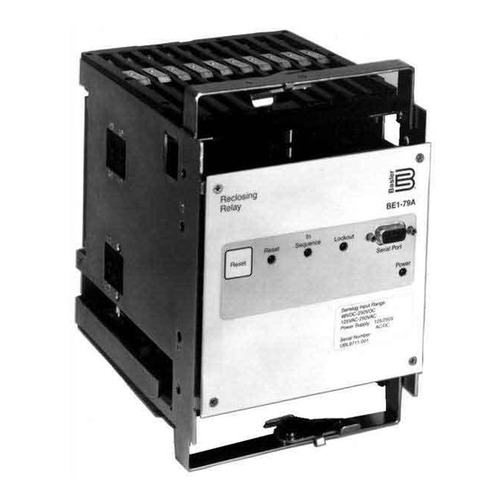
SECTION 2 • CONTROLS AND INDICATORS FRONT PANEL Figure 2-1 shows the front panel controls and indicators for the BE1-79A Multiple Shot Reclosing Relay. Figure 2-1. BE1-79A Front Panel The following paragraphs describe each control and indicator and refer to the call-outs of Figure 2-1. -
Page 13: Style Configuration Switches
ACR11B operation. For simplicity, recloser styles ACR11B, ACR11C, ACR11D, ACR11E, and ACR11F will be referred to as ACR11B throughout this manual. Figure 2-2 illustrates the location of switches S1, S2, and S3. Figure 2-2. Style Configuration Switches BE1-79A Controls And Indicators... -
Page 14: Instantaneous Reclose Jumper Switch
Figure 2-3 illustrates the location of switch S4, used to select internal or external jumpering, and S5, used to select normally open or normally closed operation of the RS contact. Figure 2-3. Instantaneous Reclose Jumper Switch and RS contact selection switch BE1-79A Controls And Indicators... -
Page 15: Section 3 • Functional Description
This section describes the hardware, circuit operation, and software functional descriptions. HARDWARE The BE1-79A relay is available in an S1 cradle and case(200 series) or an S2 cradle without a case(100 series). 200 series Description This BE1-79A consists of a fabricated steel and phenolic enclosure with a draw-out cradle assembly. The case has the same overall dimensions as a Basler Electric or General Electric S1 case. -
Page 16: Inputs
Inputs There are four types of inputs to the BE1-79A relay. They are: • Operating AC/DC Power • Contact Sensing Inputs • Reset Switch • Serial Communication Port Operating AC/DC Power. Operating power for the internal circuitry is applied to the isolated internal switching power supply. -
Page 17: Microprocessor
This serial port provides the means to configure and read relay settings. Microprocessor All reclosing and communication functions are coordinated by the microprocessor. The BE1-79A uses an eight bit microprocessor with integral ROM (read only memory) and RAM (random access memory). - Page 18 The BE1-79A has ten outputs. The function of each output depends on the operating configuration of the relay. Tables 3-3 and 3-4 provide a description of each output for each relay configuration. Table 3-3. Outputs Description for ACR11A Operation Output...
-
Page 19: Interconnections
Figure 3-2 illustrates the interconnection of the contact sensing inputs, relay outputs, style configuration switches, and instantaneous reclose jumper switch in the BE1-79A relay. Figure 3-2 shows the relay configured for an ACR11A application. Figure 3-3 shows the relay configured for an ACR11B application with an instantaneous recloser jumper. - Page 20 E X T D 2 6 3 3 - 0 6 04-18-00 C 1 0 Figure 3-2. Relay Interconnections For ACR11A Applications BE1-79A Functional Description...
- Page 21 E X T D2633-05 04-18-00 C 1 0 Figure 3-3. Relay Interconnections For ACR11B Applications BE1-79A Functional Description...
-
Page 22: Recloser Operation
Time Reached Resetting Reset Timer Expired Lockout Reclose Time Reached Manual 5 2 A Reclose Reset Reclose Attempts Time Reached D o n e ? Reset D2588-06 05-06-97 Reclose 5 2 B Figure 3-4. Power-Up Flow Chart BE1-79A Functional Description... -
Page 23: Reset
The reclose and reset timer settings of Basler reclosing relays such as the BE1-79 and BE1-79M are based on the breaker opening that immediately precedes each reclose and reset setting. This is not the case with the BE1-79A. - Page 24 Figure 3-5. BE1-79A Reclose Settings Example 3-10 BE1-79A Functional Description...
- Page 25 T i m e ? Lockout Reset Complete? 5 2 B Rec 4 Lockout Issue Reclose Perform Signal 5 2 A Lockout 5 2 B Final Reset Time? Reclose Complete? Reset Figure 3-6. Reclosing Flow Chart BE1-79A Functional Description 3-11...
-
Page 26: Section 4 • Communication
> is returned for a valid command, ? is returned for an invalid command. Commands received by the BE1-79A consist of two types: requests for information and changes to operating parameters. Commands to change parameters are identified by an equal sign (=). The operating parameters to the right of the equal sign are intended to replace the current operating parameters related to the command. -
Page 27: Command Descriptions
If C is entered, the EXIT command will be aborted and programming may continue. It is important to make all changes to relay parameters before executing the EXIT command. This ensures that all intended settings are executed. BE1-79A Communication... -
Page 28: Obtaining Help Information Through The Serial Port
S command can be used to make a record of the relay settings after they have been set. Example 1. Obtain a report of the relay settings. SP-79A1 5,10 SP-79A2 15,20 SP-79A3 25,30 SP-79A4 35,40 SP-79ALO 45,50 SP-79ARS D,0,5 SP-ALM 2 > Table 4-1. Default Switch Settings. Switch Default BE1-79A Communication... -
Page 29: Reclose And Reset Timer Setting Command
The state of the RS contact, which can be D or E. D indicates de-energized.. E indicates energized. apply time: Time from the start of the reclose cycle until the RS contact is applied. The apply time BE1-79A Communication... -
Page 30: Alarm Output Command
2 selects Relay Fail and Lockout Relay Information Command RG-VER Command Purpose: Read information about relay hardware/software configuration. Syntax: RG-VER Comments: Transmitting the RG-VER command will cause the relay to respond with the relay model number and the software version and date. BE1-79A Communication... -
Page 31: Section 5 • Installation
Because the relay is of solid-state design, it does not have to be mounted vertically. Any convenient mounting angle may be chosen. The BE1-79A is available in an S1 cradle with case or an S2 cradle. The S2 cradle is intended for installation in an existing S2 case. - Page 32 Figure 5-1. BE1-79A S1 Case Overall Dimensions BE1-79A Installation...
- Page 33 (72.1) 8.25 (209.6) 8.63 (219.1) 4.13 4.31 (104.8) (109.5) .25 (6.35) DIA. 3.03 4 P L A C E S (77.0) 6.06 D 1 4 2 7 - 0 4 (154.0) 1-23-93 Figure 5-2. S1 Case Cutout Dimensions BE1-79A Installation...
- Page 34 Figure 5-3. S1 Case, Rear View, Terminal Connections BE1-79A Installation...
- Page 35 Figure 5-4. Typical Connections for ACR11A Application BE1-79A Installation...
- Page 36 Figure 5-5. Typical Connections for ACR11B Application BE1-79A Installation...
-
Page 37: Motor Input Voltage
No adjustment is required for the motor voltage applied at terminals 5 and 6. The applied voltage can range from 120 to 240 Vac or 125 to 250 Vdc. These terminals serve as the input to the BE1-79A power supply and control functions. -
Page 38: Timing Cams
18 cycles for transmission voltages (including breaker operating time). The inherent delay of the BE1-79A relay is 22 to 48 milliseconds when set at a time delay of zero. The reclose timers may be adjusted in increments of 0.1 seconds which is 6 cycles on a 60 Hertz system. -
Page 39: Communication Connections And Settings
The relay settings are fixed at 9600,8N1 where 9600 = baud rate, 8 = number of data bits, N = no parity, and 1 = 1 stop bit. Since the communication settings of the BE1-79A are fixed, you must adjust your communication program settings to match the relay settings. -
Page 40: Relay Installation
Adjust the Style Configuration Switches and the Instantaneous Reclose Jumper Switch to the correct setting for your application. Step 2. Insert the BE1-79A relay and close the cradle latches locking the relay into the case. Step 3. Install the connection plugs. -
Page 41: Section 6 • Testing
SECTION 6 • TESTING INTRODUCTION You may prefer to test your relay before installation. To function test BE1-79A relays, perform the procedure provided in the following paragraphs. Figure 6-1 illustrates the necessary connections for testing relays configured for ACR11A style operation. The connections diagram for testing relays configured for ACR11B operation is provided in Figure 6-2. -
Page 42: Delayed Reclose Testing
Place switch S1 in the 52 B position and verify that after 15 seconds, Reclose indicator L2 lights for three seconds. Step 7. Place S1 in the 52A position and verify that after 20 seconds, the front panel Reset LED and the Reset indicator L1 illuminates. BE1-79A Testing... - Page 43 Auxiliary Contact - Closed in Reset External Jumpers RS Contact - Closes, opens at time set by user Delayed First Reclose Contact closes when terminal 7 is energized Instantaneous First Reclose Figure 6-1. Test Connections For ACR11A Style Relays BE1-79A Testing...
- Page 44 Lockout B E 1 - 7 9 A Reset D2588-09 04-18-00 Auxiliary Contact - Closed in Reset RS Contact - Closes, opens at time set by user Optional Reclose Output Figure 6-2. Test Connections For ACR11B Style Relays BE1-79A Testing...
-
Page 45: Power Holdup Circuit Testing
Part Number 9 3102 00 101 Relays Remove 120 Vac operating power from terminals 5 and 6. Measure the time from when the operating power is removed until the RS contacts (terminals 9, 10) close. The time should be 1.3 seconds or greater. BE1-79A Testing... -
Page 46: Maintenance
SECTION 7 • MAINTENANCE GENERAL BE1-79A Multiple Shot Reclosing Relays require no preventative maintenance. However, testing should be performed according to scheduled practices. If the relay fails to function properly, contact the Technical Support Services Department of Basler Electric for a return authorization number before returning the relay for service.
Need help?
Do you have a question about the BE1-79A and is the answer not in the manual?
Questions and answers