Table of Contents
Advertisement
Quick Links
Advertisement
Table of Contents

Related Manuals for ADLINK Technology nanoX-TCR


Summary of Contents for ADLINK Technology nanoX-TCR
- Page 1 (Computer-on-Module) Reference Manual P/N 50-1Z108-1000...
- Page 2 Notice Page DISCLAIMER ADLINK Technology, Incorporated makes no representations or warranties with respect to the contents of this manual or of the associated ADLINK products, and specifically disclaims any implied warranties of merchantability or fitness for any particular purpose. ADLINK shall under no circumstances be liable for incidental or consequential damages or related expenses resulting from the use of this product, even if it has been notified of the possibility of such damages.
-
Page 3: Table Of Contents
Power Interface ........................22 Power Management........................22 Video Interfaces........................23 LVDS ..........................23 SDVO ..........................23 Audio Interface ........................23 Ethernet Interface ........................23 I²C™ Bus ..........................24 PCI Express™ ..........................24 System Management Bus (SMBus) ..................24 CAN Bus [Optional]........................24 GPIO............................25 Watchdog Timer..........................28 Temperature Sensor ........................29 nanoX-TCR Reference Manual... - Page 4 Table 3-3. I/O Address Map ....................21 Table 3-4. SMBus Reserved Addresses ................24 Table 3-5. COM Express A-B Connector Signal Descriptions..........25 Table 4-1. BIOS Setup Menus....................33 Table A-1. Technical Support Contact Information ..............43 Reference Manual nanoX-TCR...
-
Page 5: Chapter 1 About This Manual
Chapter 1 About This Manual Purpose of this Manual This manual is for designers of systems based on the nanoX-TCR (Computer-on-Module). This manual contains information that permits designers to create an embedded system based on specific design requirements. Information provided in this reference manual includes: •... - Page 6 Atmel Corporation and the ATMEGA168V-10AU chip used as the board controller Datasheet: http://www.atmel.com/dyn/resources/prod_documents/2545S.pdf NOTE If you are unable to locate the datasheets using the links provided, search the internet to find the manufacturer’s web site and locate the documents you need. Reference Manual nanoX-TCR...
-
Page 7: Chapter 2 Product Overview
Type 10 Up to 4 The nanoX-TCR utilizes the Mini form factor and the Type 10 pinout definition, featuring one high- performance COM Express connector that ensures stable data throughput. The single-connector interfaces of the Type 1 and Type 10 pinouts free systems completely from legacy signals while solving the space constraints of the Mini form factor. -
Page 8: Com Express Architecture
CPUs, chipsets, and multiprocessor systems. The placement of the shielded 220-pin connectors and the mounting holes are identical between these four footprints. Note: Measurements are in millimeters Figure 2-1. Mini, Compact, Basic and Extended Form Factors Reference Manual nanoX-TCR... -
Page 9: Product Description
USB 2.0 ports and up to two SATA ports as well as embedded interfaces for CAN (optional), GPIO, and I2C. The nanoX-TCR provides an optional Solid State Drive through the SATA1 port and one Gigabit Ethernet interface through the Intel 82574IT Gigabit Ethernet controller chip (external magnetics required) using PCIe Port1 from the CPU. - Page 10 -Maximum pixel clock rate up to 160MHz • Provide LVDS flat panel outputs -Resolutions up to 1280x768 @ 60Hz -Minimum pixel clock rate of 19.75MHz -Maximum pixel clock rate of 80MHz -Pixel color depths of 18 and 24 bits Reference Manual nanoX-TCR...
- Page 11 ♦ • Supports bit rate up to 1 Mbps • Supports 32 message objects • Miscellaneous Real Time Clock (RTC) with external battery ♦ Watchdog Timer (WDT) ♦ CPU Temperature Sensor ♦ OEM Logo Screen (Splash) ♦ nanoX-TCR Reference Manual...
-
Page 12: Block Diagram
COM Express Connector - Rows A and B LVDS HD Audio 2X PCIe X1 GPIO (8) USB 2.0 (6) SMBus SDVO Gb Ethernet SATA (1 or 2) LVDS DDC I2C USB Client CAN (Optional) Figure 2-2. Functional Block Diagram Reference Manual nanoX-TCR... -
Page 13: Major Components (Ics)
Chapter 2 Product Overview Major Components (ICs) Table 2-2 lists the major integrated circuits on the nanoX-TCR, including a brief description of each IC. Figures 2-3 show the locations of the major ICs. Table 2-2. Major Integrated Circuit Descriptions and Functions Chip Type Mfg. - Page 14 Power ROHM BD9591MWV Power Management Supplies power Management IC Chipset to main system (U115) blocks Power Regulator ROHM BD9595MUV Power Regulator Rectifies sudden (U116 - on change in power bottom side; see load from Figure 2-4]) BD9591MWV Reference Manual nanoX-TCR...
-
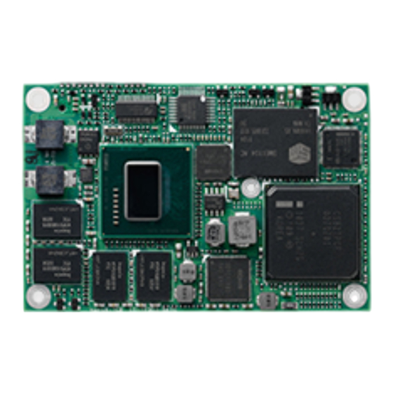
Page 15: Figure 2-3. Component Locations (Top Side)
U44 - DDR2 SDRAM U45 - DDR2 SDRAM U46 - DDR2 SDRAM U113 - Temperature Sensor U116 - Power Regulator CN2 - COM Express Type 10 Connector (see connector table) U113 Figure 2-4. Component Locations (Bottom Side) nanoX-TCR Reference Manual... -
Page 16: Connector
Board Description Access CN2 – COM Express A-B Bottom 220-pin connector for Northbridge Video and Southbridge I/O functions. Key: CN2A - COM Express pins A1-A110 CN2B - COM Express pins B1-B110 Figure 2-5. Connector Locations (Bottom Side) Reference Manual nanoX-TCR... -
Page 17: Specifications
55.00 mm (2.17 inches) solutions are 15.00mm (0.43 inches) for Length 84.00 mm (3.31 inches) the heatsink and 11.00mm (0.59 inches) for the heatspreader. Figure 2-7 on page 16 for an illustration of the cooling solution stack heights. nanoX-TCR Reference Manual... -
Page 18: Mechanical Specifications
Chapter 2 Product Overview Mechanical Specifications The following figure provides mechanical dimensions of the nanoX-TCR. Figure 2-6 shows the top-side view of the board with measurements between mounting holes. 3.15 (80.00mm) 2.99 (76.00mm) 2.74 (69.60mm) 1.14 (28.96mm) 0.49 (12.50mm) 0.00 0.16 (4.00mm) -
Page 19: Power Specifications
Chapter 2 Product Overview Power Specifications Table 2-5 provides the power requirements for the nanoX-TCR with 600MHz, 1.3GHz, and 1.6GHz CPUs and a 430 watt power supply. Table 2-5. Power Supply Requirements Parameter 600MHz E620T CPU 1.3GHz E660T CPU 1.6GHz E680T CPU... -
Page 20: Thermal/Cooling Requirements
Product Overview Thermal/Cooling Requirements The nanoX-TCR is designed to operate at its maximum CPU speeds of 600MHz, 1.3GHz, and 1.6GHz and requires a thermal solution to cool the CPU, PCH, and voltage regulators. ADLINK offers one optional cooling solution as well as a heat spreader platform on which to build a cooling solution. (See Table 2-7 descriptions of cooling options.) -
Page 21: Chapter 3 Hardware
The main chips used in the nanoX-TCR may provide more features or options than are listed for the nanoX-TCR, but some of these features or options are not supported on the module and will not function as specified in the chip documentation. -
Page 22: Cpu
Memory The nanoX-TCR employs two ranks of four system DRAM memory chips, which provide up to 2GB of extended memory, supporting aggressive power management to reduce power consumption, shallow self- refresh and a new deep self-refresh, proactive page closing policies to close unused pages, and partial writes through data mask pins. -
Page 23: Interrupt Channel Assignments
Legend: D = Default, X = Fixed, O = Optional NOTE The IRQs for the Ethernet, Video, and USB are automatically assigned by the BIOS Plug and Play logic. Local IRQs assigned during initialization can not be used by external devices. nanoX-TCR Reference Manual... -
Page 24: Memory Map
Reserved for Extended BIOS 000E0000h 000EFFFFh Extended System BIOS Area 000F0000h 000FFFFFh System BIOS Area (Storage and RAM Shadowing) Top 32, 64, or 128MB of Shared memory of Integrated Graphics enabled Physical Memory FFE00000h FFFFFFFFh System Flash Reference Manual nanoX-TCR... -
Page 25: I/O Address Map
Slave DMA Controller #2 00E0-00EF System reserved 00F0-00FF Math Coprocessor 01F0-01F7 SATA Controller 02F8-02FF Serial Port 2 (COM1)* 03B0-03BB Video (monochrome) 03F8-03FF Serial Port 1 (COM0)* 04D0-04D1 Edge/Level Trigger PIC 0CF9 Reset Control Register *Located on the baseboard. nanoX-TCR Reference Manual... -
Page 26: Com Express A-B Connector
GPIO LPC Interface The nanoX-TCR offers the LPC (Low Pin Count) bus through the CPU. Many devices already exist for this Intel defined bus. The LPC bus corresponds approximately to a serialized ISA bus yet with a significantly reduced number of signals. Because of the software compatibility to an ISA bus, I/O extensions such as additional serial ports can be easily implemented on an application specific baseboard using this bus. -
Page 27: Video Interfaces
Digital Input signals (AC/HDA_SDIN) support up to two codecs. Ethernet Interface The nanoX-TCR supports one Gigabit Ethernet interface. The Ethernet interface is implemented from the 82574IT Ethernet controller and provides one GLAN interface, which occupies PCI Express port 1. The Ethernet function supports multi-speed operation at 10/100/1000 Mbps and operates in full-duplex at all supported speeds or half duplex at 10/100 Mbps while adhering to the IEEE 802.3x flow control... -
Page 28: I²C™ Bus
PCI Express ™ The nanoX-TCR offers four (4x) PCI Express x1 ports (ports 0-3) through the COM Express A-B connector, originating from the CPU. Ports 2 and 3 can be configured to support PCI Express edge cards or ExpressCards, supporting up to 2.5 Gb/s bandwidth in each direction. The first x1 port (port 0) acts as the connection between the CPU and the PCH and cannot be used as a PCIe port. -
Page 29: Gpio
Hardware GPIO The nanoX-TCR provides GPIO (General Purpose I/O) pins for custom use through the COM Express A-B connector. Use the ADLINK Intelligent Device Interface (AIDI) Library to configure the GPIO interface. AIDI driver information is available in the Utilities link of the nanoX-TCR product page at: http://www.adlinktech.com. - Page 30 Ethernet - PCIE1 of CPU) of CPU) PCIE3_TX- (Occupied by PCIE3_RX- (Occupied by Gb Gb Ethernet - Ethernet - PCIE1 PCIE1 of CPU) of CPU) PCIE2_TX+ (Occupied by PCH - PCIE0) B61 PCIE2_RX+ (Occupied by PCH - PCIE0) Reference Manual nanoX-TCR...
- Page 31 (Hot Plug Detect - PU 10k 3.3V Standby) SPI_POWER (3.3 V S5 Standby) B91 DDIO_PAIR5+ (SDVO_TVCLKINP) SPI_MISO DDIO_PAIR5- (SDVO_TVCLKINN) GPO0 DDIO_PAIR6+ (SDVO_STALLP) SPI_CLK DDIO_PAIR6- (SDVO_STALLN) SPI_MOSI RSVD (Not Connected) RSVD (Not Connected) SPI_CS# (SPI Chip Select for Carrier) nanoX-TCR Reference Manual...
-
Page 32: Watchdog Timer
Watchdog Code example – ADLINK provides a source code example (AIDI demo program) in the Utilities link of the nanoX-TCR product page illustrating how to control the WDT. The code example can be easily copied to your development environment to compile and test or make any desired changes before compiling. -
Page 33: Temperature Sensor
Hardware Temperature Sensor The nanoX-TCR provides a temperature sensor to ensure the health of your embedded system with built-in support for monitoring and control of system temperatures, fan speeds, and critical module voltage levels. The AIDI Library provides simple APIs at the application level to support these functions and adds alarm functions when voltage or temperature levels exceed the upper or lower limits set by the user. - Page 34 Chapter 3 Hardware Reference Manual nanoX-TCR...
-
Page 35: Chapter 4 Bios Setup
Entering BIOS Setup (Serial Port Console) This section describes how to enter the BIOS setup through a remote serial terminal or PC. Turn on the power supply to the nanoX-TCR and enter the BIOS Setup Utility using a local video display. -
Page 36: Oem Logo Utility
OEM Logo Utility The nanoX-TCR BIOS supports a graphical logo utility, which allows the user to customize the boot screen image. The graphical image can be a company logo or any custom image the user wants to display during the boot process. -
Page 37: Bios Setup Menus
BIOS Setup BIOS Setup Menus This section provides illustrations of the six top-level setup screens in the nanoX-TCR BIOS Setup Utility. Below each illustration is a bullet list of the screen’s submenus and setting selections. The setting selections are presented in brackets after each submenu or menu item, and the optimal default settings are presented in bold. -
Page 38: Advanced Bios Setup Screen
Previous Values F3 : Optimized Defaults F4 : Save & Exit ESC: Exit Version X.XX.XXXX. Copyright (C) 20XX American Megatrends, Inc. Figure 4-2. Advanced BIOS Setup Screen • Legacy OpROM Support Launch PXE OpROM [Disabled; Enabled] ♦ Reference Manual nanoX-TCR... - Page 39 EHCI Hand-off [Disabled; Enabled] • H/W Monitor LM9163 Pc Health Status ♦ • System temperature +XX C • CPU temperature (By PECI) +XX C • Fan1 Speed • Fan2 Speed N/AXXXX RPM • Fan3 Speed • Fan4 Speed nanoX-TCR Reference Manual...
- Page 40 Console Redirection [Disabled; Enabled] • Console Redirection Settings [Same as COM0] NOTE The serial port console is not hardware protected. Diagnostic software that probes hardware addresses may cause a loss or failure of the serial console functions. Reference Manual nanoX-TCR...
-
Page 41: Chipset Bios Setup Screen
Enabled, 8MB; Enabled, 16MB; Enabled, 32MB; Enabled, 48MB; Enabled, 64MB] MSAC Mode Select [Enabled, 512MB; ♦ Enabled, 256MB; Enabled, 128MB] Boot Display Configuration ♦ • Boot Display Device [Integrated LVDS; External DVI/HDMI] • Flat Panel Type [640x480 18bit(generic); nanoX-TCR Reference Manual... - Page 42 PCI Express Ports Configuration ♦ • PCI Express Root Port 0 [Disabled; Enabled] • PCI Express Root Port 1 [Disabled; Enabled] • PCI Express Root Port 2 [Disabled; Enabled] • PCI Express Root Port 3 [Disabled; Enabled] Reference Manual nanoX-TCR...
-
Page 43: Boot Bios Setup Screen
Boot Option #1 [P1-SILICONMOTION SM631GX8AB; UEFI: Hard Drive; Disabled] ♦ Boot Option #2 [P1-SILICONMOTION SM631GX8AB; UEFI: Hard Drive; Disabled] ♦ Hard Drive BBS Priorities ♦ • Boot Option #1 [P1-SILICONMOTION SM631GX8AB; SDHC - SDC; Disabled] • Boot Option #2 [P1-SILICONMOTION SM631GX8AB; SDHC - SDC; Disabled] nanoX-TCR Reference Manual... -
Page 44: Security Bios Setup Screen
Optimized Defaults F4 : Save & Exit ESC: Exit Version X.XX.XXXX. Copyright (C) 20XX American Megatrends, Inc. Figure 4-5. Security BIOS Setup Screen • Password Description Administrator Password [Create New Password] ♦ User Password [Create New Password] ♦ Reference Manual nanoX-TCR... -
Page 45: Save & Exit Bios Setup Screen
• Save Options Save Changes ♦ • Save configuration [Yes; No] Discard Changes (F7 key can be used for this operation.) ♦ • Load Previous Values [Yes; No] Restore Defaults ♦ • Load Optimized Defaults [Yes; No] nanoX-TCR Reference Manual... - Page 46 Chapter 4 BIOS Setup Save as User Defaults ♦ • Save configuration? [Yes; No] Restore User Defaults ♦ • Restore User Defaults? [Yes; No] • Boot Override P1-SILICONMOTION SM631GX8AB ♦ SDHC - SDC ♦ UEFI: Hard Drive ♦ Reference Manual nanoX-TCR...
-
Page 47: Appendix A Technical Support
Appendix A Technical Support ADLINK Technology, Inc. provides a number of methods for contacting Technical Support listed in the Table A-1 below. Requests for support through Ask an Expert are given the highest priority, and usually will be addressed within one working day. - Page 48 Address: 84 Genting Lane #07-02A, Cityneon Design Centre, Singapore 349584 Tel: +65-6844-2261 Fax: +65-6844-2263 Email: singapore@adlinktech.com ADLINK Technology Singapore Pte. Ltd. (Indian Liaison Office) Address: No. 1357, "Anupama", Sri Aurobindo Marg, 9th Cross, JP Nagar Phase I, Bangalore - 560078, India Tel: +91-80-65605817 Fax: +91-80-22443548 Email: india@adlinktech.com...
-
Page 49: Index
............23 I2C specification ..........1 expansion buses ............ 5 LPC specification ..........1 PCIe specification ..........1 features list ............5 SATA specification .........1 Gigabit Ethernet SATA controller description ........9 interface ............ 6 interface ............. 6 specification .............1 nanoX-TCR Reference Manual... - Page 50 ..........20 OEM Logo Utility (Splash) ......7 Real Time Clock (RTC) ........7 SATA .............. 6 Splash Screen (OEM Logo) ......32 temperature sensor .......... 7 USB ports ............6 video interfaces ..........6 Watchdog Timer ........7 Reference Manual nanoX-TCR...
- Page 51 Mouser Electronics Authorized Distributor Click to View Pricing, Inventory, Delivery & Lifecycle Information: ADLINK Technology nanoX-TCR-L-13 nanoX-TCR-L-16 nanoX-TCR-R-13 nanoX-TCR-R-16 nanoX-TCR-R-14 nanoX-TCR-R-06 nanoX-TCR-L-06 NANOX-TCR-E680T-2G nanoX-TCR-E660T-1G nanoX-TCR-E620T-2G nanoX-TCR-E680T-1G THS-nXTCR-B...
Need help?
Do you have a question about the nanoX-TCR and is the answer not in the manual?
Questions and answers