
Related Manuals for Stryker ARGAIOS


Summary of Contents for Stryker ARGAIOS
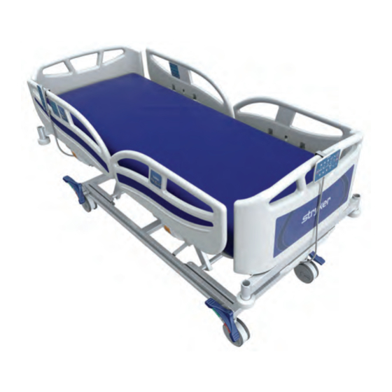
- Page 1 A A R R G G A A I I O O S S E E l l e e c c t t r r i i c c H H o o s s p p i i t t a a l l B B e e d d M M a a i i n n t t e e n n a a n n c c e e M M a a n n u u a a l l 7600-000-050 7600-000-100...
- Page 3 S S y y m m b b o o l l s s Refer to instruction manual/booklet Operating instructions / Consult instructions for use General warning Caution Warning; crushing of hands Warning; crushing of feet Do not insert lift pole Headboard and footboard orientation Do not store items under the bed Gatch positioning...
- Page 4 Adult patient Direct current Alternating current Dangerous voltage Unit provides terminal for connection of a potential equalization conductor. The potential equalization conductor provides direct connection between the unit and potential equalization busbar of the electrical installation. Protective Earth terminal Protection from liquid splash I I P P X X 4 4 Type B applied part In accordance with European Directive 2012/19/EU on Waste Electrical and Electronic...
- Page 5 T T a a b b l l e e o o f f C C o o n n t t e e n n t t s s Warning/Caution/Note Definition ..........................3 Summary of safety precautions ..........................4 Pinch points................................5 Introduction ................................6 Product description ..............................6...
- Page 6 Siderail assembly ..............................57 Siderail release latch assembly ..........................58 Headboard and footboard assembly ........................59 EMC information ..............................60 HM-17-314 ................................64 HM-17-16 ................................65 HM-17-156 ................................66 HM-17-310/HM-17-311 ............................67 HM-17-313 ................................68 HM-17-312 ................................69 HM-17-304 ................................70 HM-17-303 ................................71 HM-17-305 ................................72 SK-7600 REV 06...
- Page 7 W W a a r r n n i i n n g g / / C C a a u u t t i i o o n n / / N N o o t t e e D D e e f f i i n n i i t t i i o o n n The words W W A A R R N N I I N N G G , C C A A U U T T I I O O N N , and N N O O T T E E carry special meanings and should be carefully reviewed.
- Page 8 S S u u m m m m a a r r y y o o f f s s a a f f e e t t y y p p r r e e c c a a u u t t i i o o n n s s Always read and strictly follow the warnings and cautions listed on this page.
- Page 9 P P i i n n c c h h p p o o i i n n t t s s F F i i g g u u r r e e 1 1 – – A A R R G G A A I I O O S S 2 2 5 5 0 0 p p i i n n c c h h p p o o i i n n t t s s SK-7600 REV 06...
- Page 10 I I n n t t r r o o d d u u c c t t i i o o n n This manual assists you with the operation or maintenance of your Stryker product. Read this manual before operating or maintaining this product.
- Page 11 E E x x p p e e c c t t e e d d s s e e r r v v i i c c e e l l i i f f e e A A R R G G A A I I O O S S 2 2 5 5 0 0 has a ten year expected service life under normal use conditions and with appropriate periodic maintenance.
- Page 12 E E l l e e c c t t r r i i c c a a l l r r e e q q u u i i r r e e m m e e n n t t s s Duty cycle 2 mins of actuation and 18 mins idle C C l l a a s s s s I I E E q q u u i i p p m m e e n n t t : : Equipment that protects against electrical shock and does not solely rely on basic insulation, but...
- Page 13 Stryker reserves the right to change specifications without notice. S S t t a a n n d d a a r r d d s s a a p p p p l l i i e e d d...
- Page 14 P P r r o o d d u u c c t t i i l l l l u u s s t t r r a a t t i i o o n n Accessory sleeve Linen tray (option) Lower leg section Backrest...
- Page 15 C C o o n n t t a a c c t t i i n n f f o o r r m m a a t t i i o o n n Contact your Stryker Customer Service: Stryker Medical International Kayseri Serbest Bölge Şubesi...
- Page 16 S S e e r r i i a a l l n n u u m m b b e e r r l l o o c c a a t t i i o o n n SK-7600 REV 06...
- Page 17 P P r r e e v v e e n n t t i i v v e e m m a a i i n n t t e e n n a a n n c c e e At a minimum, check all items listed during annual preventive maintenance for all Stryker Medical products. You may need to perform preventive maintenance checks more frequently based on your level of product usage.
- Page 18 Enclosure is free from wear, tear, stresses and mechanical damage High potential test 1500 VAC (trip current not more than 10 mA) No rust or corrosion of parts Control boxes are not damaged or cracked Actuator functionality Labels for legibility, proper adherence, and integrity Product serial number: Completed by: Date:...
- Page 19 T T r r o o u u b b l l e e s s h h o o o o t t i i n n g g P P r r o o b b l l e e m m P P o o s s s s i i b b l l e e C C a a u u s s e e S S o o l l u u t t i i o o n n Bed does not operate...
- Page 20 P P r r o o b b l l e e m m P P o o s s s s i i b b l l e e C C a a u u s s e e S S o o l l u u t t i i o o n n Control box beeps while actuators are Control box actuator position...
- Page 21 SK-7600 REV 06...
- Page 22 S S e e r r v v i i c c e e F F o o w w l l e e r r ( ( b b a a c c k k r r e e s s t t ) ) a a c c t t u u a a t t o o r r r r e e p p l l a a c c e e m m e e n n t t T T o o o o l l s s r r e e q q u u i i r r e e d d : : •...
- Page 23 G G a a t t c c h h ( ( l l e e g g r r e e s s t t ) ) a a c c t t u u a a t t o o r r r r e e p p l l a a c c e e m m e e n n t t T T o o o o l l s s r r e e q q u u i i r r e e d d : : •...
- Page 24 2. Support the head end litter cross brace (A) to support the head end litter (Figure 5). 3. Power down the bed and unplug the power cord from the wall outlet. 4. Using a small flat screwdriver, gently push in both locking tabs to remove the cable retainer on the head end lift actuator electrical connector.
- Page 25 2. Support the foot end litter cross brace (A) to support the foot end litter (Figure 6). 3. Power down the bed and unplug the power cord from the wall outlet. 4. Using a small flat screwdriver, gently push in both locking tabs to remove the cable retainer on the foot end lift actuator electrical connector.
- Page 26 • Torque wrench with 5 mm hex bit (9.5 Nm) • 5 mm hex wrench • Needle nose pliers • Hammer P P r r o o c c e e d d u u r r e e : : 1.
- Page 27 F F i i g g u u r r e e 7 7 – – N N o o n n - - s s t t e e e e r r c c a a s s t t e e r r S S t t e e e e r r ( ( h h e e a a d d l l e e f f t t ) ) c c a a s s t t e e r r r r e e p p l l a a c c e e m m e e n n t t T T o o o o l l s s r r e e q q u u i i r r e e d d : : •...
- Page 28 9. Use a small floor jack to lift the base frame cross tube to loosen the non-steer caster. 10. Grasp the opposite brake/steer pedal and pull outward about four inches (100 mm) to remove and discard the non-steer caster. N N o o t t e e - - Note the position of the label on the mounting shaft of the old caster for reinstallation of the replacement caster. 11.
- Page 29 4. Using a 3/8 in. drive ratchet and 13 mm socket, remove and save the nut and washers from the top of the fifth wheel assembly. 5. Remove and discard the fifth wheel assembly. 6. Reverse steps to reinstall. N N o o t t e e - - You may have to compress the fifth wheel assembly slightly to reinstall. 7.
- Page 30 • Hammer • 3/8 in. drive ratchet • 13 mm socket • 13 mm combination wrench P P r r o o c c e e d d u u r r e e : : 1. Apply the brakes. 2.
- Page 31 P P r r o o c c e e d d u u r r e e : : 1. Apply the brakes. 2. Raise the product to the highest height position. 3. Power down the bed and unplug the power cord from the wall outlet. 4.
- Page 32 7. Using a 13 mm socket, remove and save the bolt (C), washers (D, E), and nut (F) that secures the bottom of the lower leg section locking mechanism to the litter frame (Figure 12). 8. Remove and discard the lower leg section locking mechanism (B) (Figure 12). 9.
- Page 33 N N u u r r s s e e c c o o n n t t r r o o l l p p e e n n d d a a n n t t r r e e p p l l a a c c e e m m e e n n t t T T o o o o l l s s r r e e q q u u i i r r e e d d : : •...
- Page 34 4. Turn the battery off using the nurse control. 5. Raise and lock the lower leg section in the highest position. 6. Using a small flat screwdriver, un-clip the actuator cable retainer (A) from the control box (Figure 13). 7. Remove and save the actuator cable retainer. 8.
- Page 35 5. Using diagonal pliers, cut and discard the cable tie that secures the battery cable to all of the actuator cables. 6. Using a #2 Phillips screwdriver, unscrew the four screws (A) that secure the battery to the litter frame (Figure 14). N N o o t t e e - - Support the battery while removing the screws so the battery does not fall.
- Page 36 F F i i g g u u r r e e 1 1 5 5 – – P P o o w w e e r r c c o o r r d d H H e e a a d d e e n n d d s s i i d d e e r r a a i i l l h h o o o o p p r r e e p p l l a a c c e e m m e e n n t t T T o o o o l l s s r r e e q q u u i i r r e e d d : : •...
- Page 37 F F i i g g u u r r e e 1 1 6 6 – – H H e e a a d d e e n n d d s s i i d d e e r r a a i i l l h h o o o o p p F F o o o o t t e e n n d d s s i i d d e e r r a a i i l l h h o o o o p p r r e e p p l l a a c c e e m m e e n n t t T T o o o o l l s s r r e e q q u u i i r r e e d d : : •...
- Page 38 B B r r a a k k e e s s y y s s t t e e m m Q Q u u a a n n t t i i t t y y I I t t e e m m N N u u m m b b e e r r N N a a m m e e YM-FUTUREBALT-003-BY...
- Page 39 Q Q u u a a n n t t i i t t y y I I t t e e m m N N u u m m b b e e r r N N a a m m e e HM-01-83 150 mm no steer lock antistatic single integral...
- Page 40 Q Q u u a a n n t t i i t t y y I I t t e e m m N N u u m m b b e e r r N N a a m m e e YM-HM-02-025 Transfer bar Ø8 plastic hole HM-09-30...
- Page 41 B B a a s s e e a a n n d d l l e e g g a a s s s s e e m m b b l l y y Q Q u u a a n n t t i i t t y y I I t t e e m m N N u u m m b b e e r r N N a a m m e e...
- Page 42 Q Q u u a a n n t t i i t t y y I I t t e e m m N N u u m m b b e e r r N N a a m m e e HM-08-07 M10 prevailing torque type hexagon nut...
- Page 43 B B a a s s e e a a n n d d l l e e g g a a s s s s e e m m b b l l y y w w i i t t h h 5 5 t t h h w w h h e e e e l l ( ( o o p p t t i i o o n n ) ) Q Q u u a a n n t t i i t t y y I I t t e e m m N N u u m m b b e e r r...
- Page 44 L L i i t t t t e e r r / / f f r r a a m m e e a a s s s s e e m m b b l l y y Q Q u u a a n n t t i i t t y y I I t t e e m m N N u u m m b b e e r r...
- Page 45 Q Q u u a a n n t t i i t t y y I I t t e e m m N N u u m m b b e e r r N N a a m m e e HM-11-31 Ø10 rue clip YM-HM-02-401...
- Page 46 B B u u m m p p e e r r r r o o l l l l e e r r a a s s s s e e m m b b l l y y Q Q u u a a n n t t i i t t y y I I t t e e m m N N u u m m b b e e r r...
- Page 47 B B e e d d e e x x t t e e n n d d e e r r a a s s s s e e m m b b l l y y Q Q u u a a n n t t i i t t y y I I t t e e m m N N u u m m b b e e r r N N a a m m e e...
- Page 48 Q Q u u a a n n t t i i t t y y I I t t e e m m N N u u m m b b e e r r N N a a m m e e YM-02-55 Footboard pin socket HM-08-38...
- Page 49 H H i i - - L L o o a a c c t t u u a a t t o o r r s s Q Q u u a a n n t t i i t t y y I I t t e e m m N N u u m m b b e e r r N N a a m m e e...
- Page 50 C C o o n n t t r r o o l l b b o o x x a a n n d d b b a a t t t t e e r r y y Q Q u u a a n n t t i i t t y y I I t t e e m m N N u u m m b b e e r r...
- Page 51 L L i i t t t t e e r r f f o o w w l l e e r r ( ( b b a a c c k k r r e e s s t t ) ) a a s s s s e e m m b b l l y y Q Q u u a a n n t t i i t t y y I I t t e e m m N N u u m m b b e e r r...
- Page 52 Q Q u u a a n n t t i i t t y y I I t t e e m m N N u u m m b b e e r r N N a a m m e e HM-08-06 M8 fibered nut HM-07-03...
- Page 53 L L i i t t t t e e r r s s e e a a t t a a s s s s e e m m b b l l y y Q Q u u a a n n t t i i t t y y I I t t e e m m N N u u m m b b e e r r N N a a m m e e...
- Page 54 L L i i t t t t e e r r g g a a t t c c h h ( ( l l e e g g r r e e s s t t ) ) a a s s s s e e m m b b l l y y Q Q u u a a n n t t i i t t y y I I t t e e m m N N u u m m b b e e r r...
- Page 55 Q Q u u a a n n t t i i t t y y I I t t e e m m N N u u m m b b e e r r N N a a m m e e HM-05-005 M10 x 35 mm hex head bolt HM-06-88...
- Page 56 F F o o w w l l e e r r ( ( b b a a c c k k r r e e s s t t ) ) a a c c t t u u a a t t o o r r Q Q u u a a n n t t i i t t y y I I t t e e m m N N u u m m b b e e r r...
- Page 57 G G a a t t c c h h ( ( l l e e g g r r e e s s t t ) ) a a c c t t u u a a t t o o r r Q Q u u a a n n t t i i t t y y I I t t e e m m N N u u m m b b e e r r...
- Page 58 S S i i d d e e r r a a i i l l h h e e a a d d e e n n d d a a s s s s e e m m b b l l y y Q Q u u a a n n t t i i t t y y I I t t e e m m N N u u m m b b e e r r...
- Page 59 N N u u m m b b e e r r ( ( l l e e f f t t ) ) N N u u m m b b e e r r ( ( r r i i g g h h t t ) ) S S i i d d e e r r a a i i l l l l a a m m i i n n a a t t e e Yellow signal HM-20-891...
- Page 60 S S i i d d e e r r a a i i l l f f o o o o t t e e n n d d a a s s s s e e m m b b l l y y Q Q u u a a n n t t i i t t y y I I t t e e m m N N u u m m b b e e r r...
- Page 61 S S i i d d e e r r a a i i l l a a s s s s e e m m b b l l y y Q Q u u a a n n t t i i t t y y I I t t e e m m N N u u m m b b e e r r N N a a m m e e...
- Page 62 S S i i d d e e r r a a i i l l r r e e l l e e a a s s e e l l a a t t c c h h a a s s s s e e m m b b l l y y Q Q u u a a n n t t i i t t y y I I t t e e m m N N u u m m b b e e r r...
- Page 63 H H e e a a d d b b o o a a r r d d a a n n d d f f o o o o t t b b o o a a r r d d a a s s s s e e m m b b l l y y Q Q u u a a n n t t i i t t y y I I t t e e m m N N u u m m b b e e r r...
- Page 64 E E M M C C i i n n f f o o r r m m a a t t i i o o n n G G u u i i d d a a n n c c e e a a n n d d M M a a n n u u f f a a c c t t u u r r e e r r ’ ’ s s D D e e c c l l a a r r a a t t i i o o n n - - E E l l e e c c t t r r o o m m a a g g n n e e t t i i c c E E m m i i s s s s i i o o n n s s A A R R G G A A I I O O S S 2 2 5 5 0 0 is intended for use in an electromagnetic environment specified below.
- Page 65 G G u u i i d d a a n n c c e e a a n n d d M M a a n n u u f f a a c c t t u u r r e e r r ’ ’ s s D D e e c c l l a a r r a a t t i i o o n n - - E E l l e e c c t t r r o o m m a a g g n n e e t t i i c c I I m m m m u u n n i i t t y y Mains power quality should be that of a typical for 0.5 cycle at 0°,...
- Page 66 Portable and mobile RF communications equipment should be used no closer to any part of A A R R G G A A I I O O S S 2 2 5 5 0 0 , including cables, than the recommended separation distance calculated from the equation appropriate for the...
- Page 67 Field strengths from fixed transmitters, such as base stations for radio (cellular/cordless) telephones and land mobile radios, amateur radio, AM and FM radio broadcast, and TV broadcast cannot be predicted theoretically with accuracy. To assess the electromagnetic environment due to fixed RF transmitters, an electromagnetic site survey should be considered.
- Page 68 H H M M - - 1 1 7 7 - - 3 3 1 1 4 4 HM-17-314 SK-7600 REV 06...
- Page 69 H H M M - - 1 1 7 7 - - 1 1 6 6 HM-17-16 SK-7600 REV 06...
- Page 70 H H M M - - 1 1 7 7 - - 1 1 5 5 6 6 HM-17-156 SK-7600 REV 06...
- Page 71 H H M M - - 1 1 7 7 - - 3 3 1 1 0 0 / / H H M M - - 1 1 7 7 - - 3 3 1 1 1 1 HM-17-310/HM-17-311 SK-7600 REV 06...
- Page 72 H H M M - - 1 1 7 7 - - 3 3 1 1 3 3 HM-17-313 SK-7600 REV 06...
- Page 73 H H M M - - 1 1 7 7 - - 3 3 1 1 2 2 HM-17-312 SK-7600 REV 06...
- Page 74 H H M M - - 1 1 7 7 - - 3 3 0 0 4 4 HM-17-304 HM-17-304 SK-7600 REV 06...
- Page 75 H H M M - - 1 1 7 7 - - 3 3 0 0 3 3 HM-17-303 SK-7600 REV 06...
- Page 76 H H M M - - 1 1 7 7 - - 3 3 0 0 5 5 HM-17-305 SK-7600 REV 06...
- Page 78 Stryker Medical 3800 E. Centre Avenue Portage, MI 49002 SK-7600 REV 06 2021-08 WCR: AA.11...
Need help?
Do you have a question about the ARGAIOS and is the answer not in the manual?
Questions and answers