
Related Manuals for Stryker Adel Maternity Bed Series


Summary of Contents for Stryker Adel Maternity Bed Series
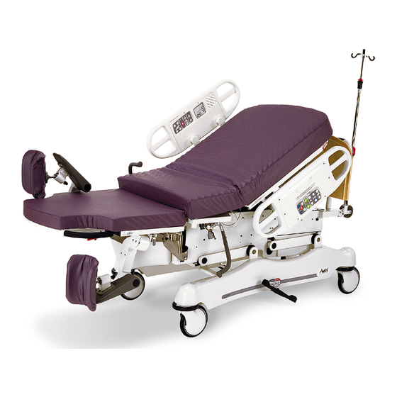
- Page 1 Adelr Maternity Bed Model 4700 & 5012 OPERATIONS MANUAL For Parts or Technical Assistance 1−800−327−0770...
-
Page 2: Table Of Contents
Table of Contents Introduction ................Specifications . -
Page 3: Introduction
NOTE This provides special information to make maintenance easier or important instructions clearer. To ensure its proper use and the safety of patients and staff, the Stryker Adelr Maternity Bed has been marked with the following caution and warning labels: DANGER Explosion Hazard −... -
Page 4: Bed Symbols
Bed Symbols Warning, Refer to Service/Maintenance Manual Alternating Current Type B Equipment: equipment providing a particular degree of protection against elec- tric shock, particularly regarding allowable leakage current and reliability of the protec- tive earth connection. Class 1 Equipment: equipment in which protection against electric shock does not rely on BASIC INSULATION only, but which includes an additional safety precaution in that means are provided for the connection of the EQUIPMENT to the protective earth con- ductor in the fixed wiring of the installation in such a way that ACCESSIBLE METAL... -
Page 5: Safety Tips And Guidelines
Introduction SAFETY TIPS AND GUIDELINES Before operating the Stryker Adel Maternity Bed, it is important to read and understand all information in this manual. Carefully read and strictly follow the safety guidelines listed on this page. It is important that all users have been trained and educated on the inherent hazards associated with the usage of electric beds. -
Page 6: Unpacking Instructions And Set−Up Procedures
Refer to unpacking instructions attached to the bed inside the crate. SET−UP PROCEDURES It is important that the Stryker Adelr Maternity Bed is working properly before it is put into service. The follow- ing list will help ensure that each part of the bed is tested. -
Page 7: Bed Illustration
Bed Illustration WARNING Potential pinch points... -
Page 8: Siderail Operation Guide
Siderail Operation Guide OPERATING SIDERAILS To engage the head end siderail, grasp the rail and swing it upward to full height. When the siderail is being raised, it does not lock in the intermediate position. To lower the siderail, push in the release handle and rotate the siderail until it locks in the intermediate position. - Page 9 Siderail Operation Guide INSIDE SIDERAIL FUNCTION GUIDE (CONTINUED) 1. Push to turn the television on and to select a channel. 2. Push to increase the television volume. 3. Push to decrease the television volume. 1. Push to turn the room light on. Push again to turn off.
- Page 10 Siderail Operation Guide OUTSIDE SIDERAIL FUNCTION GUIDE 1. Push to raise Fowler (back rest). 2. Push to raise bed height. 3. Push to raise foot section. 4. Push to lower Fowler (back rest). 5. Push to lower bed height. 6. Push to lower foot section. 1.
- Page 11 Communication Pendant Operation Guide...
- Page 12 Motion Pendant Operation Guide...
- Page 13 Motion Pendant with Nurse Call Operation Guide...
-
Page 14: Operating Bed Features
Operating Bed Features USING THE BRAKE AND STEER PEDALS The brake pedals are located at the center of the base frame on both sides of the bed. To engage the brakes, depress the pedal to the brake position. To disengage the brakes, depress the pedal to the neutral position. The steer pedal is located at the head end of the bed. -
Page 15: Removing The Head Board
Operating Bed Features REMOVING THE HEAD BOARD To remove the head board, lift it straight up and off the bed. To replace the head board, align the plastic inserts on the bottom of the head board with the pins on the bed and lower the head board until it completely engages the pins. -
Page 16: Night Light Usage
Operating Bed Features NIGHT LIGHT USAGE The bed is equipped with a night light to illuminate the floor area around the bed. There is a switch on the light to turn it on and off. OPERATING THE GLIDEAWAY FOOT SECTION/ATTACHABLE CALF SUPPORTS Rotate the foot rest into position by pulling it out and up over the foot end mattress until it clicks into place. -
Page 17: Birthing Bed Positioning
Operating Bed Features BIRTHING BED POSITIONING Position the patient’s feet in the foot rests. Raise or lower the foot rests to a position comfortable for the patient. Remove the foot section and tuck the drape into the drainage pan. Raise the bed to a comfortable height by pressing the “Bed−Up” control on the siderail and position the patient’s perineum out and over the edge of the seat section. -
Page 18: Using Accessories
Using Optional Accessories USING LEG SUPPORTS To use full−length leg supports on the bed, insert the leg support bar into the receptacle near the labor grips at the perineal edge. USING THE LABOR BAR To use the labor bar, insert it into the holes on each side of the seat section, under the mattress at the perineal edge. -
Page 19: Using The Permanently Attached I.v. Pole
Using Optional Accessories OPERATING OPTIONAL 3−STAGE PERMANENTLY ATTACHED I.V. POLE DETAIL OF I.V. POLE LATCH DETAIL OF I.V. POLE GRIP NOTE The 3−stage permanently attached I.V. pole is an option and can only be installed at the head end of the bed. To use the 3−stage permanently attached I.V. -
Page 20: Cleaning
If these types of products are used to clean Stryker patient handling equipment, measures must be taken to insure the stretchers are rinsed with clean water and thoroughly dried following cleaning. Failure to properly rinse and dry the stretchers will leave a cor- rosive residue on the surface of the stretcher, possibly causing premature corrosion of critical components. -
Page 21: Preventative Maintenance Checklist
Preventative maintenance should be performed at a minimum of annually. A preventative maintenance pro- gram should be established for all Stryker Medical equipment. Preventative maintenance may need to be performed more frequently based on the usage level of the product. -
Page 22: Limited Warranty
If requested by Stryker, products or parts for which a warranty claim is made shall be returned prepaid to Stryker’s factory. Any improper use or any alteration or repair by others in such manner as in Stryker’s judgement affects the product materially and adversely shall... -
Page 23: Return Authorization
Stryker will perform all service during regular business hours (9−5) * Replacement parts and labor for products under PM contract will be discounted. ** Does not include any disposable items, I.V. poles (except for Stryker HD permanent poles), mattresses, or damage re- sulting from abuse. - Page 24 European Representative Stryker EMEA RA/QA Director Stryker France ZAC Satolas Green Pusignan Av. De Satolas Green 69881 MEYZIEU Cedex France 6300 S. Sprinkle Road, Kalamazoo, MI 49001−9799 (800) 327−0770 www.strykermedical.com DH 10/03 4700−009−001 REV B...
Need help?
Do you have a question about the Adel Maternity Bed Series and is the answer not in the manual?
Questions and answers