Advertisement
AXS
TM
Neuro Driver
Instructions for Use
DESCRIPTION:
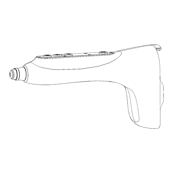
The AXS
Neuro Driver (PDCMF-1000-1) is a battery-powered fixation driver outfitted with a pencil grip, rear battery pack,
TM
and fixed collet. The driver can run in the forward and reverse directions by pressing colored LED lit buttons. The driver has the
ability to operate in both the adaptive torque limiting (ATL) and non-torque limiting (NTL) modes. The use of the mode switch
allows a change between ATL and NTL operations. The driver performs a self-check upon activation to ensure proper function
prior to use. Any detected errors will prompt the colored LED lights to emit a flashing red "error" signal, preventing further use
of the driver. The AXS
Neuro Driver is intended for use in a surgical theatre by a licensed surgeon, intending to use the
TM
fixation device on exposed, fractured, or otherwise damaged bone in the Cranial region of the body by applying rotational
energy through Stryker Universal Neuro products not included with the device.
Please note that these instructions may differ from other similar surgical drivers you have used. Also review the AXS
Driver Battery instructions prior to use of this device.
The AXS
Neuro Driver has been designed and tested to be safely operated in combination with the following accessories:
TM
•
PDCMF-BP-001 –Battery, AXS™ Neuro Driver
•
PDCMF-SC-001 –Storage and Transport Tray, AXS™ Neuro Driver
Stryker Accessories:
•
o
62-15035 Universal Neuro III AXS Screwdriver Blade, Long
o
62-15036 Universal Neuro III AXS Screwdriver Blade, Short
o
62-15020 Universal Neuro II Screwdriver Blade, for LP screws
62-15024 Universal Neuro II Screwdriver Blade, for LP screws, short
o
o
62-15000 Universal Neuro I Screwdriver Blade, for Standard Screws
o
92-62151 Universal Neuro I Screwdriver Blade, Short
o
62-50105 Universal Neuro I, II, III Adapter/Quick Drive J-Latch
o
60-12594 Twist Drill, Universal Neuro III, 1.2 X 48mm, WL4mm
o
60-12596 Twist Drill, Universal Neuro III, 1.2 X 50mm, WL6mm
The torque-limiting feature of the AXS
Neuro screws using their respective Stryker screwdriver blades.
Stryker Universal Neuro Screws:
•
56-15933 Universal Neuro III Screw, Self-drilling Ø1.5mm, L: 3mm
•
56-15934 Universal Neuro III Screw, Self-drilling Ø1.5mm, L: 4mm
•
56-15935 Universal Neuro III Screw, Self-drilling Ø1.5mm, L: 5mm
•
92-15904 Universal Neuro Screw, Cross-Pin, Self-drilling Ø1.5mm, L: 4mm
•
92-15905 Universal Neuro Screw, Cross-Pin, Self-drilling Ø1.5mm, L: 5mm
•
92-15994 Universal Neuro II Screw, Cross-Pin, Self-drilling Ø1.5mm, L: 4mm
INDICATIONS FOR USE:
Select screws and plates per Stryker's plate fixation system recommendation.
The AXS
Neuro Driver has been designed and tested to be used in conjunction with Stryker Universal Neuro fixation systems.
TM
Screws must have a diameter of 1.5 mm and a length of 3, 4, and 5 mm. Each screw must be checked by hand for tightness after
each installation.
Pro-Dex P/N 10033 Rev. A
Neuro Driver has been designed and tested to control the insertion of Stryker Universal
TM
Neuro
TM
1
Advertisement
Table of Contents

Subscribe to Our Youtube Channel
Related Manuals for Stryker AXS Neuro Driver


Summary of Contents for Stryker AXS Neuro Driver
- Page 1 The AXS Neuro Driver has been designed and tested to be used in conjunction with Stryker Universal Neuro fixation systems. Screws must have a diameter of 1.5 mm and a length of 3, 4, and 5 mm. Each screw must be checked by hand for tightness after each installation.
- Page 2 Use of a screwdriver blade or drill other than approved Stryker screwdriver blades or drills with the AXS Neuro Driver should never be attempted as it may result in damage to the driver and/or driver blade/drill.
- Page 3 1) Drill Pilot Hole (if necessary): The collet has been designed to interface only with hex coupled Stryker Universal Neuro blades and J-latch adapter. To install the J-latch adapter, pull the collet grip (nose cone) back and hold in that position while inserting the J-latch adapter into the collet shaft.
- Page 4 3) Battery Installation, Self-Diagnostics Check: PDCMF-BP-001 The driver has been designed to interface only with the Battery, AXS Neuro Driver . To install the battery, orient it such that the metal contacts on the battery pack visually align with the contacts inside the end of the driver housing. Slide the bottom of the battery into the mating interface hook at the bottom of the housing.
- Page 5 Clean, disinfect and sterilize the Stryker accessories in accordance with the instructions described in the respective IFUs: •...
-
Page 6: Troubleshooting
De-ionized water, 93°C (199.4°F) Sterilizing the AXS Neuro Driver: Sterilization to be performed with the AXS Neuro Driver and Stryker accessories inside the Storage and Transport • Tray (PDCMF-SC-001). • Sterilization to be performed with devices nested in a JK341/JK388 Aesculap container. - Page 7 If a problem arises that is not covered in the TROUBLESHOOTING section above, you may contact Stryker Customer Service at (800) 962-6558 for assistance. In order to initiate return of an item, please contact Stryker Customer Service at (800) 962-6558 to obtain a Return Material Authorization (RMA) number.
- Page 8 Neuro Driver Instructions for Use SYMBOLS: Battery/Driver Alignment Arrow Do not immerse Fast Forward button Caution Slow Forward button Type B applied equipment Reverse button Consult instructions for use Mode button Keep Dry Serial Number Autoclave Volts Direct Current Catalogue Number Batch Code Temperature Range for Shipping and Storage Quantity...
-
Page 9: Technical Specifications
Neuro Driver Instructions for Use TECHNICAL SPECIFICATIONS: Product Number: PDCMF-1000-1 Classification: Complies with ANSI/AAMI 60601-1:2005(R) 2012/A1:2012, CSA C22.2 NO 60601-1:14, IEC 60601- 1:2005+AMD1:2012 Voltage: 8.0 VDC Mode of operation: Non-continuous – S3 20% (1 second on, 4 seconds off, estimated average duty cycle) Protection against harmful ingress of water: Ordinary –... - Page 10 Neuro Driver Instructions for Use EMC Table 1 (IEC 60601-1-2, Ed 4) Guidance and manufacturer’s declaration - electromagnetic emissions The PDCMF-1000-1 series is intended for use in the electromagnetic environment specified below. The customer or the user of the PDCMF-1000-1 series should assure that it is used in such an environment. Emissions test Compliance Electromagnetic environment –...
- Page 11 Neuro Driver Instructions for Use EMC Table 4 (IEC 60601-1-2, Ed 4) Guidance and manufacturer’s declaration - electromagnetic immunity (for ME equipment and ME systems that are not Life-Supporting) The PDCMF-1000-1 series is intended for use in the electromagnetic environment specified below. The customer or the user of the PDCMF- 1000-1 series should assure that it is used in such an environment.
-
Page 12: Test Level
Neuro Driver Instructions for Use EMC Table 6 (IEC 60601-1-2, Ed 4) Recommended separation distance between Portable and mobile RF communications equipment and the PDCMF-1000 series The PDCMF-1000-1 series is intended for use in an electromagnetic environment in which radiated RF disturbances are controlled. - Page 13 Pro-Dex Inc., as the manufacturer does not assume any liability for direct or consequential damage resulting from improper use or handling, in particular as a result of failure to comply with the operating instructions or as a result of incorrect care or maintenance. Manufactured by Pro-Dex Distributed by Stryker Pro-Dex, Inc. Stryker Craniomaxillofacial 2361 McGaw Ave.
Need help?
Do you have a question about the AXS Neuro Driver and is the answer not in the manual?
Questions and answers