
Related Manuals for Stryker Atlas 660


Summary of Contents for Stryker Atlas 660
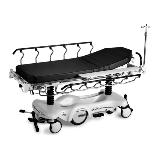
- Page 1 IMPORTANT File in your maintenance records Atlas Transport Stretcher Model 660 MAINTENANCE MANUAL For Parts or Technical Assistance 1−800−327−0770 (Option 2)
-
Page 2: Table Of Contents
Table of Contents Introduction Specifications ................Warning / Caution / Note Definition . - Page 3 Table of Contents Assembly Drawings and Parts Lists (Continued) Release Pedal Assembly ..............Pump Pedal Assembly .
-
Page 4: Introduction
0 to 30_ Trendelenburg \ Reverse Trendelenburg +18 to −18° Stryker reserves the right to change specifications without notice. WARNING / CAUTION / NOTE DEFINITION The words WARNING, CAUTION and NOTE carry special meanings and should be carefully reviewed. WARNING Alerts the reader about a situation, which if not avoided, could result in death or serious injury. -
Page 5: Preventative Maintenance
Preventative maintenance should be performed at a minimum of annually. A preventative maintenance pro- gram should be established for all Stryker Medical equipment. Preventative maintenance may need to be performed more frequently based on the usage level of the product. -
Page 6: Cleaning
Position the Fowler at 45_, place the unit in full reverse Trendelenburg (foot end down), raise the siderails, and place the I.V. poles and push handles in the up position. Stryker Medical recommends the standard hospital surgical cart washer for power washing Model 660 stretchers. - Page 7 If these types of products are used to clean Stryker patient handling equipment, measures must be taken to insure the stretchers are rinsed with clean water and thoroughly dried following cleaning. Failure to properly rinse and dry the stretchers will leave a cor- rosive residue on the surface of the stretcher, possibly causing premature corrosion of critical components.
-
Page 8: Service Information
Service Information CASTER COVER INSTALLATION AND REMOVAL Double Prongs Looking through the larger of the two side cut−outs, align the cover with the axle nut or bolt head, as shown. Single Prong Push down on the opposite side of the cover until the single prong engages the caster horn. -
Page 9: Foot End Release Pedal Replacement
Service Information FOOT END RELEASE PEDAL REPLACEMENT Required Tools: Needle Nose Pliers 1. Apply the stretcher brakes. 2. Disconnect the release pedal return springs from the foot end release pedals. 3. Remove the rue ring cotters and the clevis pins connecting the foot end release pedals to the mounting bracket. -
Page 10: Big Wheel Side Control Brake Rod Removal
Service Information BIG WHEEL SIDE CONTROL BRAKE ROD REMOVAL Required Tools: Hammer 7/32” Punch Needle Nose Pliers String or Bungee Cords 1. Pump the litter up to full height. 2. Lift the base hood and support it from the litter using string or bungee cords. 3. -
Page 11: Brake Ring Removal
Service Information BRAKE RING REMOVAL Required Tools: 9/16” Socket w/Extension 3/8” Drive Ratchet Needle−Nose Pliers String or Bungee Cords 1. Pump the litter up to full height. 2. Lift the base hood and support it from the litter using string or bungee cords. 3. -
Page 12: Big Wheel Hubcap Removal
Service Information BIG WHEEL HUBCAP REMOVAL Required Tools: Large Standard Screwdriver 1. Using a large standard screwdriver, pry evenly around the entire edge of the Big Wheel hubcap until it pops off the mounting studs on the wheel. CAUTION Do not attempt to pull off the hubcap after prying up only one side. Damage to the slots on the hubcap or the mounting studs on the wheel could result. -
Page 13: Big Wheel Removal
Service Information BIG WHEEL REMOVAL Required Tools: Large Standard Screwdriver Small Standard Screwdriver String or Bungee Cords 1. Lift the base hood and separate the Velcro holding it to the base frame. Support the hood from the litter using bungee cords so it is out of the way. 2. -
Page 14: Side Control Big Wheel Linkage Assembly Removal
Service Information SIDE CONTROL BIG WHEEL LINKAGE ASSEMBLY REMOVAL Required Tools: 1/4” Punch Hammer Needle−Nose Pliers String or Bungee Cords 1. Pump the litter up to full height. 2. Lift the base hood and support it from the litter using string or bungee cords. 3. -
Page 15: Removal Of Excess Air From The Hydraulic System
Service Information REMOVAL OF EXCESS AIR (VACUUM) FROM THE HYDRAULIC SYSTEM 1. Verify all hydraulic linkages are secure and operating properly. 2. Using the pump pedal, actuate the system several times to force the air through the system. The jack should now raise properly. - Page 16 Service Information FOOT END HYDRAULIC JACK REMOVAL (BIG WHEEL BASE WITH 3−SIDED CONTROLS) Required Tools: 1/2” Socket 3/8” Drive Ratchet Pliers 1. Remove the litter top from the stretcher (see page 16). 2. Lift the base hood off the base frame. 3.
-
Page 17: Head End Hydraulic Jack Removal
Service Information HEAD END HYDRAULIC JACK REMOVAL Required Tools: 1/2” Socket w/Extension 3/8” Drive Ratchet 1. Remove the litter top from the stretcher (see below). 2. Using a 1/2” socket with extension and a 3/8” drive ratchet, remove the two hex head screws holding the jack base to the stretcher base frame. -
Page 18: Pneumatic Fowler Adjustment
Service Information PNEUMATIC FOWLER ADJUSTMENT Required Tools: 3/32 Hex Allen Wrench 1/2 Socket w/Ratchet 1/8 Hex Allen Wrench Channel Lock Pliers 5/32 Hex Allen Wrench Towel or Cloth 7/16 Open End Wrench Thread ”Loctite” Adjustment Procedure: 1. Refer to drawings 1711−31−10 & 1711−131−20 (Pneumatic Fowler Assembly, page 58 &... -
Page 19: Quick Reference Replacement Parts List
Quick Reference Replacement Parts List PART NAME PART NUMBER Cam Replacement Kit, Big Wheel ........1040−700−003 Foot Board/Chartholder . - Page 20 Big Wheel End Control Base Assembly Assembly part number 1040−015−105 (reference only) HEAD END...
- Page 21 Big Wheel End Control Base Assembly DETAIL A HEAD END See Detail A...
- Page 22 Big Wheel End Control Base Assembly Item Part No. Part Name Qty. 0021−166−000 Set Screw 0023−150−000 Hex Washer Hd. Screw 0023−288−000 Hex Washer Hd. Screw 0026−273−000 Clevis Pin 0025−330−000 Clevis Pin 0027−020−000 Rue Ring Cotter 0029−007−000 Dual Lock 0029−009−000 Dual Lock 0042−020−000 Collar 0081−330−000...
- Page 23 Base Assembly w/Standard Brakes (Big Wheel Base) Assembly part number 1040−003−405 (reference only)
- Page 24 Base Assembly w/Standard Brakes (Big Wheel Base) Item Part No. Part Name Qty. 0005−039−000 Step Bolt 0011−262−000 Washer 0016−035−000 Nylock Hex Nut 0016−049−000 Nylock Hex Nut 0023−025−000 Hex Washer Hd. Screw 0027−012−000 Hitch Pin 0027−022−000 Rue Ring Cotter Pin 0028−037−000 External Retaining Ring 0038−439−000 Extension Spring...
- Page 25 0753−010−020 8” Caster Assembly Item Part No. Part Name Qty. 0715−002−025 Wheel 0003−099−000 Hex Hd. Cap Screw 0753−010−021 Caster Horn w/Bearing 0016−060−000 Centerlock Nut...
-
Page 26: Drive Link Assembly
1040−003−185 Drive Link Assembly Item Part No. Part Name Qty. 0753−003−098 Semi−Tubular Rivet 0753−003−102 Brake Cam 1040−003−174 Brake Rod Drive Link 1040−003−076 Cam Drive Link... -
Page 27: Brake Rod Assembly
1040−003−191 Brake Rod Assembly (Big Wheel Base) Item Part No. Part Name Qty. 0026−067−000 Slotted Spring Pin 1040−003−113 Brake Rod 0753−003−099 Butterfly “V” Pedal... - Page 28 Base with Dual Side Hydraulics (Big Wheel Base) Assembly part number 1040−005−400 (reference only) Insert pump ram into keyhole slot on both ends. Lower pump connecting rod weldment onto pump ram as shown. Insert item P to retain pump connecting rod. 0753−002−025 Constant Descent Jacks 0753−002−080 Variable Descent Jacks...
- Page 29 Base with Dual Side Hydraulics (Big Wheel Base) Insert spring hook thru hole in pump connecting rod weldment Attach other hook to return spring hook as shown. Insert spring hook into hook on release pedal assembly. Insert other hook into pump connecting rod weldment as shown.
- Page 30 Base with Dual Side Hydraulics (Big Wheel Base) Insert head end release rod into release valve assembly as shown DETAIL A SEE DETAIL B Insert foot end release rod into release valve assembly as shown DETAIL B SEE DETAIL A Item Part No.
-
Page 31: Release Pedal Assembly
0753−004−101 Release Pedal Assembly Item Part No. Part Name Qty. 0025−079−000 Rivet 0753−004−004 Release Pedal Weldment 0753−004−029 Release Pedal Standoff 0753−004−320 Release Pedal Support 0753−004−321 Release Pedal Support 1061−201−127 Short Uni Pedal... -
Page 32: Pump Pedal Assembly
0753−005−185 Head End Pump Pedal Assembly Item Part No. Part Name Qty. 0026−343−000 Groove Pin 0715−001−140 Vinyl Tube 0753−005−044 Pump Pedal Bushing 0753−005−180 Head End Pump Pedal Weldment 0753−201−126 Pump Pedal... -
Page 33: Base Assembly With Three Side Hydraulics (Fifth Wheel Base)
Base with 3−Side Hydraulics Asssembly part number 0753−005−310 (reference only) FOOT END Insert spring hook thru slots in pump pedal Attach other end onto jack tower as shown... - Page 34 Base with 3−Side Hydraulics Item Part No. Part Name Qty. 0011−023−000 Washer 0014−071−000 Washer 0023−288−000 Hex Washer Hd. Screw 0027−031−000 Cotter Pin 0038−497−000 Extension Spring (page Foot End Release Pedal Ass’y 0753−005−044 Pump Pedal Bushing 0753−005−063 Foot End Mtg. Bracket 0753−005−074 Pivot Pin 0753−005−075...
-
Page 35: Release Pedal Assembly
Foot End Release Pedal Assembly Assembly part number 0753−004−223 (reference only) Item Part No. Part Name Qty. 0026−132−000 Clevis Pin 0027−020−000 Rue Ring Cotter 0027−022−000 Rue Ring Cotter 0052−822−000 Snap−In Nyliner 0753−004−028 Release Pedal Return Spring 0753−004−038 Foot Release Rod 0753−004−039 Head Release Rod 0753−004−124... -
Page 36: Pump Pedal Assembly
0753−005−173 Foot End Pump Pedal Assembly Item Part No. Part Name Qty. 0026−343−000 Groove Pin 0715−001−140 Clear Vinyl Tubing 0753−005−044 Pump Pedal Bushing 0753−005−171 Foot End Pedal Weldment 0715−201−126 Plastic Pump Pedal... -
Page 37: Cam Bracket Assembly
Cam Bracket Assembly Assembly part number 1040−006−201 (reference only) -
Page 38: Cam Bracket Assembly
Cam Bracket Assembly Item Part No. Part Name Qty. 0014−004−000 Washer 0014−063−000 Washer 0023−262−000 Clevis Pin 0026−330−000 Clevis Pin 0026−341−000 Clevis Pin 0026−349−000 Clevis Pin 0027−020−000 Rue Ring Cotter 0027−025−000 Rue Ring Cotter 0081−400−000 Needle Bearing 0081−634−000 Needle Bearing 1040−006−209 Dampener 1040−006−141 Cam Pivot... -
Page 39: Big Wheel Carriage Assembly
Big Wheel Carriage Assembly Assembly part number 1040−015−101 (reference only) Item Part No. Part Name Qty. 0014−004−000 Washer 0026−341−000 Clevis Pin 0027−020−000 Rue Ring Cotter 0028−330−000 Spiral Retaining Ring 0081−011−000 Needle Bearing 1040−015−006 Carriage Return Spring 1040−015−030 Cover w/Counterweight 1040−015−038 Washer 1040−015−053 Carriage Spring Retainer... - Page 40 Big Wheel 4−Sided Control Base Assembly part number 1040−025−105 (reference only) HEAD END...
- Page 41 Big Wheel 4−Sided Control Base DETAIL A HEAD END See Detail A...
- Page 42 Big Wheel 4−Sided Control Base Item Part No. Part Name Qty. 0021−166−000 Set Screw 0023−150−000 Hex Washer Hd. Screw 0023−288−000 Hex Washer Hd. Screw 0026−273−000 Clevis Pin 0026−330−000 Clevis Pin 0027−020−000 Rue Ring Cotter 0029−007−000 Dual Lock 0029−009−000 Dual Lock 0042−020−000 Collar 0081−330−000...
-
Page 43: Side Control Big Wheel Carriage Assembly
Side Control Big Wheel Carriage Assembly Assembly part number 1040−025−101 (reference only) -
Page 44: Side Control Big Wheel Carriage Assembly
Side Control Big Wheel Carriage Assembly Item Part No. Part Name Qty. 0011−148−000 Washer 0011−525−000 Washer 0014−004−000 Washer 0026−341−000 Clevis Pin 0026−342−000 Groove Pin 0027−020−000 Rue Ring Cotter 0028−166−000 External Retaining Ring 0028−330−000 External Retaining Ring 0081−011−000 Needle Bearing 0081−175−000 Thrust Bearing 0753−003−099 Butterfly “V”... -
Page 45: Side Control Big Wheel Linkage Assembly
1040−025−010 Side Control Big Wheel Linkage Ass’y Item Part No. Part Name Qty. 0753−003−098 Flat Hd. Semi−Tubular Rivet 0753−003−117 Rod End Link 1040−025−011 Main Link 1040−025−013 Toggle Pivot Plate 1040−025−016 Main Link Cover 1040−025−020 Yoke Weldment 1040−025−018 Toggle Pivot Spacer 1040−025−027 Link Spacer... -
Page 46: Constant Descent Hydraulic Jacks
0753−002−025 Constant Descent Jacks Option 0753−001−001 Base Frame Weldment Item Part No. Part Name Qty. 0023−288−000 Hex Washer Hd. Screw 0753−002−001 Constant Descent Jack Ass’y 0753−010−007 Reservoir Clamp... -
Page 47: Base Labeling Assembly
Department Label see page 47 Specification Label FOOT END 0660−001−116 Atlas Label HEAD END Item Part No. Part Name Qty. 1040−010−134 Bellows 1040−015−004 Base Hood 0753−010−052 Foot End Pump Pedal Label 0753−010−053 Foot End Release Pedal Label 0946−201−060 Stryker Logo Label... -
Page 48: Base Labeling Assembly
Base Labeling Assembly Color Item F Brake/ Item G Item H Brake/ Item J Litter Set P/N Steer, Foot End Lift/Lower, Left Steer, Head End Lift/Lower, Right Bumper Strip 0753−010−016 0753−010−055 0753−010−017 0753−010−054 1010−700−015 0753−010−100 PURPLE 0753−010−160 0753−010−155 0753−010−170 0753−010−154 1010−700−025 0753−010−101 GREEN... -
Page 49: Litter Assembly
Litter Assembly Assembly part number 0660−230−010 (reference only) - Page 50 Litter Assembly...
- Page 51 Litter Assembly HEAD END Item Part No. Part Name Qty. Item Part No. Part Name Qty. 0003−355−000 Hex Hd. Cap Screw 0042−007−000 Collar Assembly 0003−356−000 Hex Hd. Cap Screw 0721−031−065 Hole Plug 0003−357−000 Hex Hd. Cap Screw 0753−010−026 Support Tube 0003−359−000 Hex Hd.
- Page 52 Siderail to Litter Assembly, Fold−to−Head...
- Page 53 Siderail to Litter Assembly, Fold−to−Head FOOT END...
- Page 54 Siderail to Litter Assembly, Fold−to−Head Item Part No. Part Name Qty. 1001−226−116 Pivot Bearing 1001−226−016 Pivot Bearing 1001−226−015 Pivot Sleeve 1001−226−017 Siderail Spring 1001−326−027 Right Spindle 1001−326−031 Lock Spindle Weldment, Rt. 1001−326−028 Left Spindle 1001−326−033 Lock Spindle Weldment, Lt. 1001−226−020 Siderail Spring Spacer 0025−172−000 Rivet...
- Page 55 Siderail to Litter Assembly, Fold−to−Foot...
- Page 56 Siderail to Litter Assembly, Fold−to−Foot HEAD END...
- Page 57 Siderail to Litter Assembly, Fold−to−Foot Item Part No. Part Name Qty. 1001−226−116 Pivot Bearing 1001−226−016 Pivot Bearing 1001−226−015 Pivot Sleeve 1001−226−017 Siderail Spring 1001−326−027 Right Spindle 1001−326−031 Lock Spindle Weldment, Rt. 1001−326−028 Left Spindle 1001−326−033 Lock Spindle Weldment, Lt. 1001−226−020 Siderail Spring Spacer 0025−172−000 Semi−Tubular Rivet...
- Page 58 1211−127−000 Optional Dual Siderail Latch Assembly FOOT END Item Part No. Part Name Qty. Item Part No. Part Name Qty. 0003−359−000 Hex Hd. Cap Screw 1001−226−045 Latch Spacer 0007−070−000 Truss Hd. Mach. Screw 1001−226−161 Dual Latch Cable Ass’y 0016−118−000 Nylock Nut 1001−226−142 Latch Pin 1001−226−147 Dual Latch Pivot 0038−222−000 Extension Spring...
-
Page 59: Pneumatic Fowler Assembly
Pneumatic Fowler Assembly Assembly part number 0660−031−010 (reference only) HEAD END Item Part No. Part Name Qty. 0003−360−000 Hex Hd. Cap Screw 0004−104−000 But. Hd. Cap Screw 0011−179−000 Washer 0014−021−000 Washer 0016−116−000 Hex Nut 0016−119−000 Hex Nut 0015−060−000 Metric Jam Nut 1211−131−026 Gas Spring Cap 0052−306−000... - Page 60 Pneumatic Fowler Assembly Assembly part number 1711−131−020 (reference only) Item Part No. Part Name Qty. Item Part No. Part Name Qty. 1001−001−036 Hole Plug 0016−118−000 Hex Nut 1211−231−025 Trip Bar Pivot 0004−455−000 But. Hd. Cap Screw 1501−031−013 Fowler Tube 0037−064−000 Grommet Bumper 1510−231−012 Fowler Skin (Fiberresin) 0007−070−000 Truss Hd.
-
Page 61: Stationary Foot Section Assembly
Fiberresin Stationary Foot Section Assembly Assembly part number (reference only): 1731−019−001 − 29” Wide Item Part No. Part Name Qty. 0025−171−000 Rivet 0753−010−032 29” Fiberresin Foot Section Skin 7900−001−102 Velcro Pile 24 1/2”... -
Page 62: Knee Gatch Assembly
Knee Gatch Assembly Assembly part number 1711−334−010 (reference only) HEAD END Item Part No. Part Name Qty. Item Part No. Part Name Qty. 0003−358−000 Hex Hd. Cap Screw 1001−034−131 Slider Support 0004−327−000 Soc. Hd. Cap Screw 1010−234−015 Mounting Bracket 0005−034−000 Rd. - Page 63 1001−134−019 Knee Gatch Crankscrew Assembly Item Part No. Part Name Qty. 0378−124−029 Shoulder Bolt 0938−001−175 Bearing Assembly 0938−001−177 Knob 0946−033−018 Crank Disk 1001−134−047 Knee Gatch Screw 1510−034−055 Gatch Drive Tube Assembly 1510−034−084 Screw Cover Assembly 1550−001−014 Magnet 1550−001−016 Crank Assembly 0016−118−000 Nylock Nut 0026−014−000...
- Page 64 Patient Transfer System to Litter Assembly Assembly part number 1211−132−003 (reference only) HEAD END Item Part No. Part Name Qty. 0011−418−000 Washer (page Transfer System Ass’y, Lt. (page Transfer System Ass’y, Rt. 0016−119−000 Nylock Nut 0003−360−000 Hex Hd. Cap Screw...
-
Page 65: Transfer System Assembly
1211−232−007 Patient Transfer System Assembly, Left Item Part No. Part Name Qty. (page Transfer Board Assembly 1211−132−016 Transfer Board Swivel 1211−132−020 Transfer Board Link 1211−132−031 Transfer Bd. Pivot Ass’y, Lt. 0026−076−000 Spring Pin 0026−112−000 Spring Pin 0011−350−000 Washer 1211−232−011 Transfer Bd. Arm Wldmt. 1211−132−029 Link Swivel 0014−007−000... -
Page 66: Transfer System Assembly
1211−232−008 Patient Transfer System Assembly, Right Item Part No. Part Name Qty. (page Transfer Board Assembly 1211−132−016 Transfer Board Swivel 1211−132−020 Transfer Board Link 0026−076−000 Roll Pin 0026−112−000 Roll Pin 0011−350−000 Washer 1211−132−030 Transfer Bd. Pivot Ass’y, Rt. 1211−232−012 Transfer Bd. Arm Wldmt. 1211−132−029 Link Swivel 0014−007−000... - Page 67 1211−132−009 Transfer Board Assembly Item Part No. Part Name Qty. 0025−125−000 Pop Rivet 0025−126−000 Pop Rivet 1211−132−004 Transfer Board 1211−132−017 Transfer Bd. Sleeve Wldmt. 1211−132−019 Stiffener Weldment...
- Page 68 1211−151−000 Foot End Steering Handles Assembly HEAD END Item Part No. Part Name Qty. 0003−356−000 Hex Hd. Cap Screw 0003−355−000 Hex Hd. Cap Screw 0016−118−000 Fiberlock Nut 0023−282−000 Self−Tapping Screw 0023−283−000 Self−Tapping Screw 0026−114−000 Roll Pin 1211−030−034 Cover, Hole/Slot 1211−030−037 Cover, Hole/Hole 1211−351−004 P.U.P.
- Page 69 1001−151−000 Head End Push Handles Litters with Fold−to−Head Siderails HEAD END Item Part No. Part Name Qty. 0016−035−000 Hex Nut 0004−182−000 Soc. But. Hd. Cap Screw 0004−198−000 Soc. But. Hd. Cap Screw 0926−400−142 Bumper 1001−151−013 Spacer Post 1001−151−023 Bolt−On Push Handle Socket, Lt. 1001−151−024 Bolt−On Push Handle Socket, Rt.
- Page 70 1211−351−010 Push Handle Assembly Item Part No. Part Name Qty. 1010−354−024 Stop Link 1211−151−018 Sleeve Assembly 0026−118−000 Roll Pin...
-
Page 71: Removable I.v. Pole Assembly
0390−025−000 Standard, Removable I.V. Pole Assembly Item Part No. Part Name Qty. 0024−023−000 Plastic Knob 0390−003−053 Double I.V. Ass’y 0393−003−043 Tube Assembly 0004−496−000 Soc. Hd. Cap Screw... -
Page 72: Tethered I.v. Pole Assembly
1711−117−000 Optional Tethered I.V. Assembly Item Part No. Part Name Qty. 0025−133−000 Dome Head Rivet 0025−171−000 Closed End Rivet 0034−022−000 Cord Clamp (page Tethered I.V. Pole Assembly 1211−117−021 Backing Plate 1211−117−022 I.V. Clip 1501−127−019 I.V. Plug... - Page 73 1211−117−010 Tethered I.V. Pole Assembly Item Part No. Part Name Qty. 0052−017−000 Spacer 1211−117−020 Cable Assembly 0926−400−062 Stop Sleeve 1010−059−016 I.V. Hook 1211−117−011 Extension Rod 1211−117−012 Base Tube Weldment 0004−495−000 Low Hd. Soc. Hd. Cap Screw 1211−117−016 Knob 0014−020−000 Nylon Washer 0004−232−000 Button Hd.
- Page 74 Optional 2−Stage I.V. Pole Mounting Assembly Assembly part numbers 1711−110−000 (Head End) 1711−112−000 (Foot End) FOOT END HEAD END Item Part No. Part Name Qty. 0003−356−000 Hex Hd. Cap Screw 0004−452−000 But. Hd. Cap Screw 0016−116−000 Fiberlock Nut 0016−118−000 Fiberlock Nut 1211−310−112 I.V.
- Page 75 1211−210−010 Optional 2−Stage I.V. Pole Assembly Item Part No. Part Name Qty. 0008−031−000 Soc. Hd. Cap Screw 0052−017−000 Washer 0926−400−162 Spacer 1211−210−029 2nd Stage Assembly 1001−359−013 Dampener 1001−159−028 Base Tube 1010−059−016 I.V. Hook (page I.V. Pole Latch 1001−359−112 Pivot...
- Page 76 1211−210−026 I.V. Pole Latch Assembly Item Part No. Part Name Qty. 0028−167−000 Retaining Ring 0031−004−000 Steel Ball 0038−392−000 Crest−to−Crest Spring 1211−091−034 Release Label 1211−110−018 I.V. Latch Seal 1211−110−020 Washer 1211−110−021 I.V. Latch Locking Pin 1211−110−022 I.V. Latch Guide 1211−110−024 I.V. Latch O.D. Housing 1211−110−035 Washer 1211−110−036...
- Page 77 Optional 3−Stage I.V. Pole Mounting Assembly Assembly part numbers 1711−111−000 (Head End) − 1711 1711−113−000 (Foot End) − 1711 FOOT END HEAD END Item Part No. Part Name Qty. 0003−356−000 Hex Hd. Cap Screw 0004−452−000 But. Hd. Cap Screw 0016−116−000 Flexlock Nut 0016−118−000 Fiberlock Nut...
- Page 78 1211−211−010 Optional 3−Stage I.V. Pole Assembly Item Part No. Part Name Qty. 0007−004−000 Truss Hd. Machine Screw 0026−076−000 Roll Pin 0052−017−000 Spacer 1211−210−031 2nd Stage Assembly 0926−400−162 Spacer (page 3rd Stage Assembly 1001−161−023 Base Tube 1010−059−016 I.V. Hook 1010−061−014 Collar (page I.V.
- Page 79 3−Stage I.V. Pole 3rd Stage Assembly Assembly part number 1211−110−032 (reference only) NOTE Item F, part number 1010−061−018 is left hand thread. When removing it, turn clockwise to loosen it. Item Part No. Part Name Qty. 0031−021−000 Ball 0038−303−000 Compression Spring 1010−061−013 Ball Retainer 1010−061−016...
-
Page 80: Defibrillator Tray Assembly
0926−039−000 Optional Defibrillator Tray Assembly Assembly part number 0926−039−010 (reference only) Umbrella Nut/Crosstube Detail Strap Securing Detail Item Part No. Part Name Qty. Item Part No. Part Name Qty. 0946−039−004 Tray 0946−039−003 Support Tube 0926−039−016 Crosstube 0926−001−082 Label 0025−055−000 Rivet 1010−050−021 Long Strap 0926−039−009... -
Page 81: Foot Extension/Defibrillator Tray Assembly
1010−050−100 Foot Extension/Defibrillator Tray Ass’y Assembly part number 1010−050−210 (reference only) Label Detail Label Detail Item Part No. Part Name Qty. Item Part No. Part Name Qty. 0008−049−000 Soc. Hd. Shoulder Bolt 1010−050−050 Knob 0014−020−000 Nylon Washer 1010−050−057 “Max. Weight” Label 0014−021−000 Nylon Washer 1010−050−205 Cushion Assembly... -
Page 82: Foot Board
0926−040−100 Foot Board/Chartholder Assembly Assembly part number 0926−040−010 (reference only) Item Part No. Part Name Qty. 0946−028−011 Chart Holder 0946−029−006 Foot Board 1020−030−000 Upright Oxygen Bottle Holder Ass’y Item Part No. Part Name Qty. 1020−030−011 Upright Bottle Holder 0027−012−000 Cotter Pin 1020−030−017 Specification Label... -
Page 83: Fowler X−Ray Cassette Assembly
Fowler X−Ray Cassette Mounting Assembly Assembly part number 1711−243−010 Item Part No. Part Name Qty. (page X−Ray Cassette Ass’y 0025−121−000 Rivet... - Page 84 X−Ray Cassette Assembly Assembly part numbers 1711−243−020 (reference only) Item Part No. Part Name Qty. 0926−023−069 Washer 0926−023−070 Block Assembly 0926−023−071 Bushing 1010−023−028 Tray Angle 1020−023−021 Knob Assembly 0001−030−000 Flat Hd. Mach. Screw 0014−003−000 Thrust Washer 1211−243−012 X−Ray Cassette Tray 1711−243−012 X−Ray Cassette Tray 1010−023−018...
- Page 85 1001−055−000 Heel Stirrup and Support Assembly Assembly part number 1001−055−010 (reference only) FOOT END Item Part No. Part Name Qty. 0003−359−000* Hex Hd. Cap Screw 0011−159−000 Flat Washer 0016−118−000 Nylock Hex Nut (page Stirrup Support Ass’y, Rt. (page Stirrup Support Ass’y, Lt. (page Stirrup Assembly * If the stretcher has the crank Fowler and/or crank Knee Gatch option, (2) 0003−355−000 and (2)
- Page 86 1001−055−015 Right Stirrup Support Assembly Item Part No. Part Name Qty. 0650−002−032 Lock Screw Assembly 0966−051−019 Wedge Lock, Modified 1001−055−011 Mounting Bracket 1010−055−016 Right Support Tube Wldmt. 0004−494−000 Soc. Hd. Cap Screw 0011−410−000 Washer 1211−117−016 Knob 0026−007−000 Roll Pin 0038−171−000 Compression Spring...
- Page 87 1001−055−016 Left Stirrup Support Assembly Item Part No. Part Name Qty. 0650−002−032 Lock Screw Assembly 0966−051−019 Wedge Lock, Modified 1001−055−011 Mounting Bracket 1010−055−026 Left Support Tube Ass’y 0004−494−000 Soc. Hd. Cap Screw 0011−410−000 Washer 1211−117−016 Knob 0026−007−000 Roll Pin 0038−171−000 Compression Spring...
-
Page 88: Heel Stirrup Assembly
1010−055−029 Heel Stirrup Assembly Item Part No. Part Name Qty. 0390−020−013 Stirrup 0390−020−009 Stirrup Holder Assembly 1010−055−030 Extension Tube Assembly 0024−011−000 Knob 0026−043−000 Roll Pin 0022−008−000 Drive Screw... -
Page 89: C−Spine Cassette Holder Assembly
1001−070−000 C−Spine Cassette Holder Assembly Item Part No. Part Name Qty. 1010−070−025 I.V. Adaptor 1010−070−018 Specification Label 0011−447−000 Flat Washer 0004−054−000 But. Hd. Cap Screw (page Support Pole Assembly (page Storage Bracket Ass’y 0016−118−000 Nylock Nut 0003−356−000 Hex Hd. Cap Screw 1001−070−011 Attachment Bracket 0003−355−000... - Page 90 1010−070−010 C−Spine Support Pole Assembly View A−A Item Part No. Part Name Qty. 1010−070−033 Support Tube Cap 0026−006−000 Roll Pin 1010−070−034 Support Arm Weldment 1010−070−042 Cassette Holder Weldment 1010−070−050 Adjustment Tube Weldment 1010−070−030 Base Tube Weldment 1010−070−045 Knob 0025−055−000 Pop Rivet 1010−070−044 Pivot Pin 0026−005−000...
- Page 91 1010−070−019 C−Spine Storage Bracket Assembly 6.5” (Ref.) 2” (Ref.) Item Part No. Part Name Qty. 1010−070−020 Storage Bracket Weldment 1010−070−045 Knob 1010−070−023 Storage Label...
-
Page 92: O2 Bottle Retainer Assembly
1040−010−090 Optional O@ Bottle Retainer Assembly Base Hood Item Part No. Part Name Qty. 1040−010−091 Bottle Retainer 1040−010−092 Scrulok Fastener... -
Page 93: Mattresses And Siderail Pads
Mattresses and Siderail Pads Mattress, 4” Thick x 31” Wide, Enhanced Comfort ....part # 0660−030−004 Mattress, 5” Thick x 31” Wide, Ultra Comfort . -
Page 94: Warranty
If requested by Stryker, products or parts for which a warranty claim is made shall be returned prepaid to Stryker’s factory. Any improper use or any alteration or repair by others in such manner as in Stryker’s judgement affects the product materially and adversely shall... -
Page 95: Return Authorization
Stryker will perform all service during regular business hours (9−5) * Replacement parts and labor for products under PM contract will be discounted. ** Does not include any disposable items, I.V. poles (except for Stryker HD permanent poles), mattresses, or damage re- sulting from abuse. - Page 96 European Representative Stryker EMEA RA/QA Director Stryker France ZAC Satolas Green Pusignan Av. De Satolas Green 69881 MEYZIEU Cedex France 6300 S. Sprinkle Road, Kalamazoo, MI 49001−9799 (800) 327−0770 www.strykermedical.com DH 6/04 0660−209−004 REV A...
Need help?
Do you have a question about the Atlas 660 and is the answer not in the manual?
Questions and answers