Advertisement
Quick Links
Advertisement

Related Manuals for Xilinx AC701 Si570


Summary of Contents for Xilinx AC701 Si570
- Page 1 AC701 Si570 Programming April 2015 XTP230...
-
Page 2: Revision History
NOTICE OF DISCLAIMER: The information disclosed to you hereunder (the “Information”) is provided “AS-IS” with no warranty of any kind, express or implied. Xilinx does not assume any liability arising from your use of the Information. You are responsible for obtaining any rights you may require for your use of this Information. - Page 3 AC701 Si570 Programming Overview Xilinx AC701 Board Software Requirements Setup for the AC701 Si570 Programming Programming the Si570 Correcting the Frequency Programming the FMC Si570 References Note: This presentation applies to the AC701...
- Page 4 AC701 Si570 Programming Overview Description – The AC701 board has a Silicon Labs Si570 Programmable Oscillator that defaults to 156.25 MHz. Via the IIC bus, the frequency of this device can be changed. This tutorial shows how to change the output frequency of this device.
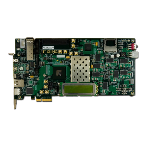
- Page 5 Xilinx AC701 Board...
- Page 6 Vivado Software Requirements Xilinx Vivado Design Suite 2015.1, Design Edition + SDK – Combined installer Note: Presentation applies to the AC701...
- Page 7 AC701 Setup Connect a USB Type-A to Micro-B cable to the USB JTAG (Digilent) connector on the AC701 board – Connect this cable to your PC...
- Page 8 AC701 Setup Connect a USB Type-A to Mini-B cable to the USB UART connector on the AC701 board – Connect this cable to your PC – Power on the AC701 board for UART Drivers Installation...
- Page 9 AC701 Setup Install USB UART Drivers – Refer to UG1033 for Installation details Note: Presentation applies to the AC701...
- Page 10 AC701 Setup Reboot your PC if necessary Right-click on My Computer and select Properties – Select the Hardware tab – Click on Device Manager Note: Presentation applies to the AC701...
- Page 11 AC701 Setup Expand the Ports Hardware – Right-click on Silicon Labs CP210x USB to UART Bridge and select Properties Note: Presentation applies to the AC701...
- Page 12 AC701 Setup Under Port Settings tab – Click Advanced – Set the COM Port to an open Com Port setting from COM1 to COM4 Note: Presentation applies to the AC701...
- Page 13 AC701 Setup Refer to UG1036 for Tera Term installation Board Power must be on before starting Tera Term Start the Terminal Program – Select your USB Com Port – Set the baud to 9600 Note: Presentation applies to the AC701...
- Page 14 Si Labs Programmable Oscillator Calculator Download ProgOscillatorSwInstall.zip Note: Presentation applies to the AC701...
- Page 15 Setup for AC701 Si570 Programming Unzip the AC701 Si570 Programming Design Files (2015.1 C) ZIP file to your C:\ drive – Available through http://www.xilinx.com/ac701 Note: Presentation applies to the AC701...
- Page 16 AC701 Si570 Programming Open a Vivado Tcl Shell: Start → All Programs → Xilinx Design Tools → Vivado 2015.1 → Vivado 2015.1 Tcl Shell Note: Presentation applies to the AC701...
- Page 17 AC701 Si570 Programming Download the Frequency Adjust bitstream with Vivado In the Vivado Tcl Shell type: cd C:/ac701_si570_programming/ready_for_download/ source freq_adjust.tcl Note: Presentation applies to the AC701...
- Page 18 AC701 Si570 Programming Open the Debug Probes Note: Presentation applies to the AC701...
- Page 19 AC701 Si570 Programming View the Debug Probes tab – Select the probes and drag to the hw_vios tab Note: Presentation applies to the AC701...
- Page 20 AC701 Si570 Programming View the VIO Cores under the Debug Probes tab – The VIO Probes show 200 MHz for the System Clock, and 156.25 MHz for the Si570 User Clock – Unsigned decimal values correspond to the frequency of each input...
- Page 21 AC701 Si570 Programming For this example, Si570_0 will be reprogrammed from 156.25 to 200 – This requires use of the SiLabs Programmable Oscillator Calculator To use the SiLabs calculator, the correct fXTAL value for each Si570 must be determined, using this equation: For this equation, –...
- Page 22 AC701 Si570 Programming The terminal window shows the current register settings for the Si570 – The power-on values will appear in the terminal window – Note the value of 0x01C2BBFE487F Note: The values reported by your Si570 may differ from those shown...
- Page 23 AC701 Si570 Programming The value, 0x01C2BBFE487F, corresponds to the contents of the Si570’s registers, 7 to 12: Note: Presentation applies to the AC701...
- Page 24 AC701 Si570 Programming Extract the HS_DIV and N1 values from 0x01C2BBFE487F: HS_DIV = 0b000 which corresponds to “4” N1 = 0b0000111 which corresponds to “8”...
- Page 25 AC701 Si570 Programming Extract the RFREQ value from 0x01C2BBFE487F : – 02BBFE487F Note: Presentation applies to the AC701...
- Page 26 AC701 Si570 Programming Open the Window Calculator Set to Scientific and Hex mode: Note: Presentation applies to the AC701...
- Page 27 AC701 Si570 Programming Enter or paste the RFREQ value, 02BBFE487F: Convert it to Decimal Note: Presentation applies to the AC701...
- Page 28 AC701 Si570 Programming Divide by 2^28 This is the value for RFREQ: Note: Presentation applies to the AC701...
- Page 29 AC701 Si570 Programming For this equation, – Fout = 156.25 – RFREQ = 43.7495808564126491546630859375 – HSDIV = 4 – N1 = 8 – Fout x HSDIV x N1 = 5000 – fXTAL = 5000 / RFREQ Note: Presentation applies to the AC701...
- Page 30 AC701 Si570 Programming For this equation, – Divide 43.7495808564126491546630859375 by 5000 – Take the reciprocal – fXTAL = 114.28680920190161752332043659281 – Ctrl-C to copy this value Note: Presentation applies to the AC701...
- Page 31 AC701 Si570 Programming Open the SiLabs Programmable Oscillator Calculator – Select the Si570 and click OK Note: Presentation applies to the AC701...
- Page 32 AC701 Si570 Programming Select Options → Advanced…...
- Page 33 AC701 Si570 Programming Paste in the value of fXTAL – The calculator will round the number appropriately – Click OK Note: Presentation applies to the AC701...
- Page 34 AC701 Si570 Programming Enter 156.25 and click the Apply Definition button...
- Page 35 AC701 Si570 Programming Set the new frequency to 200 MHz and click the Create Example button...
- Page 36 AC701 Si570 Programming Under the summary tab, the new register configurations are shown The startup register configurations will vary slightly from the actual device power-on programming Note: Presentation applies to the AC701...
- Page 37 AC701 Si570 Programming Press a key to begin entering the newly calculated values When done, press “w” Note: Presentation applies to the AC701...
- Page 38 AC701 Si570 Programming Si570 has been successfully updated Note: Presentation applies to the AC701...
- Page 39 AC701 Si570 Programming The Si570 User Clock now shows 200.00 MHz Note: Presentation applies to the AC701...
- Page 40 AC701 Si570 Programming If needed, press SW8 to reset the MicroBlaze process – Instead of reloading the bitstream; also acts as a CPU Reset...
- Page 41 Programming the FMC Si570...
- Page 42 AC701 FMC Si570 Programming Overview Description – The FMC modules, XM101, XM104, and XM105 have a Silicon Labs Si570 Programmable Oscillator that defaults to 156.25 MHz. Via the IIC bus, the frequency of this device can be changed. This tutorial shows how to change the output frequency of this device.
- Page 43 Xilinx XM101 FMC Module The XM101 board uses an on-board IIC switch...
- Page 44 Xilinx XM104 FMC Module The XM104 board has an on-board IIC switch...
- Page 45 Xilinx XM105 FMC Module The XM105 board has a direct connection to the Si570 IIC – Note: FMC_TDI and FMC_TDO (J5, 6 & 7) must be connected during configuration...
- Page 46 AC701 FMC Si570 Programming Attach your FMC board (XM101, XM104, or XM105) to the FMC HPC expansion port on the AC701 – Turn AC701 power off while installing the FMC boards...
- Page 47 AC701 FMC Si570 Programming For this example, an XM105 board has been connected to the FMC HPC port In a Vivado Tcl Shell type: cd C:/ac701_si570_programming/ready_for_download source frequency_fmc_monitor.tcl Note: Presentation applies to the AC701...
- Page 48 AC701 FMC Si570 Programming Open the Debug Probes Note: Presentation applies to the AC701...
- Page 49 AC701 FMC Si570 Programming View the Debug Probes – Select the probes and drag to the hw_vios tab Note: Presentation applies to the AC701...
- Page 50 AC701 FMC Si570 Programming An XM105 board on the FMC HPC port shows 156.25 MHz on FMC_HPC_CLK0 Note: Presentation applies to the AC701...
- Page 51 AC701 FMC Si570 Programming Under Hardware, right click on the xc7a200t_0 and select Program Device… Note: Presentation applies to the AC701...
- Page 52 AC701 FMC Si570 Programming Select a bitstream that matches your FMC Board / FMC port configuration; e.g. xm101_hpc.bit, xm104_lpc.bit, etc. – Also select the Debug Probes file, debug_nets_fmc.ltx Note: Presentation applies to the AC701...
- Page 53 AC701 FMC Si570 Programming The terminal window shows the current register settings for the Si570 – The power-on values will appear in the terminal window – Note the value of 0x01C2BC1573BB Note: The values reported by your Si570 may differ from those shown...
- Page 54 AC701 FMC Si570 Programming Use the Si570 Calibration procedure, noted earlier in this document to determine the values to enter Press a key to begin entering the newly calculated values When done, press “w” Note: Presentation applies to the AC701...
- Page 55 AC701 FMC Si570 Programming Si570 has been successfully updated Note: Presentation applies to the AC701...
- Page 56 AC701 FMC Si570 Programming The XM105 board on FMC HPC now shows 200 MHz Note: Presentation applies to the AC701...
- Page 57 AC701 with FMC XM Boards...
- Page 58 AC701 with FMC XM Boards AC701 with XM101 on the FMC HPC port Note: Presentation applies to the AC701...
- Page 59 AC701 with FMC XM Boards AC701 with XM104 on the FMC HPC port Note: Presentation applies to the AC701...
- Page 60 AC701 with FMC XM Boards AC701 with XM105 on the FMC HPC port Note: Presentation applies to the AC701...
- Page 61 References...
- Page 62 References FMC XM101 Documentation – FMC XM101 LVDS QSE Mezzanine Card • http://www.xilinx.com/products/boards-and-kits/hw-fmc-xm101-g.html – FMC XM101 LVDS QSE Mezzanine Card User Guide – UG538 • http://www.xilinx.com/support/documentation/boards_and_kits/ug538.pdf FMC XM104 Documentation – FMC XM104 Connectivity Card • http://www.xilinx.com/products/boards-and-kits/hw-fmc-xm104-g.html – FMC XM104 Connectivity Card User Guide – UG536 •...
- Page 63 References Silicon Labs – Si570 Data Sheet • http://www.silabs.com/Support%20Documents/TechnicalDocs/si570.pdf Vivado Programming and Debugging – Vivado Design Suite Programming and Debugging User Guide – UG908 • http://www.xilinx.com/support/documentation/sw_manuals/xilinx2015_1/ ug908-vivado-programming-debugging.pdf...
- Page 64 Documentation...
- Page 65 Documentation Artix-7 – Artix-7 FPGA Family • http://www.xilinx.com/products/silicon-devices/fpga/artix-7/index.htm – Design Advisory Master Answer Record for Artix-7 FPGAs • http://www.xilinx.com/support/answers/51456.htm AC701 Documentation – Artix-7 FPGA AC701 Evaluation Kit • http://www.xilinx.com/products/boards-and-kits/ek-a7-ac701-g.html – AC701 Getting Started Guide – UG967 • http://www.xilinx.com/support/documentation/boards_and_kits/ac701/2014_3/ ug967-ac701-eval-kit-getting-started.pdf – AC701 User Guide – UG952 •...
Need help?
Do you have a question about the AC701 Si570 and is the answer not in the manual?
Questions and answers