
Related Manuals for Trinamic TMCM-078


Summary of Contents for Trinamic TMCM-078
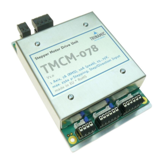
- Page 1 TMCM-078 Manual 1-axis stepper motor controller/driver module 7A RMS (9.8A peak) / 75V with step-/ direction interface Trinamic Motion Control GmbH & Co. KG Sternstraße 67 D – 20357 Hamburg, Germany http://www.trinamic.com...
-
Page 2: Table Of Contents
5.4.18 Command ‘X’ and ‘x’: firmware revision number ................. 26 5.4.19 Command ‘Y’ and ‘y’: standby current setting ................26 5.4.20 Command ‘Z’ and ‘z’: change microstep resolution ..............26 Copyright © 2008, TRINAMIC Motion Control GmbH & Co. KG... - Page 3 Table 5.8: I/Os Readout ..............................24 Table 5.9: Baud rate ................................25 Table 5.10: Adjustment of Microstep Resolution ....................... 26 Table 6.1: Document Revision ............................27 Table 6.2: Firmware Revision ............................27 Copyright © 2008, TRINAMIC Motion Control GmbH & Co. KG...
-
Page 4: Features
TMCM-078 Manual (V1.03 / September 10th, 2008) 1 Features The TMCM-078 is a single axis step / direction stepper motor driver unit. It is similar to the TMCM-IDX with higher power, more interface options and extended configuration possibilities. The TMCM-078 provides on-board DIP switches for easy configuration. -
Page 5: Life Support Policy
Specifications are subject to change without notice. Copyright © 2008, TRINAMIC Motion Control GmbH & Co. KG... -
Page 6: Electrical And Mechanical Interfacing
Name Function Positive power supply voltage GND, power Table 3.1: Power connector 3.1.2 Motor Name Function Connections for motor coil A Connections for motor coil B Table 3.2: Motor connector Copyright © 2008, TRINAMIC Motion Control GmbH & Co. KG... -
Page 7: Rs485
Optically isolated disable input Differential disable input Disable - Dis + (negative) (non inverted) Differential disable input Dis - (inverted) Table 3.4: Step-/Direction connector Figure 3.2: Opto isolated input circuit Copyright © 2008, TRINAMIC Motion Control GmbH & Co. KG... -
Page 8: I / O
(pluggable screw connectors). If open, the differential input circuit can be used (JST connector). The opto isolated interface should be not used then. Copyright © 2008, TRINAMIC Motion Control GmbH & Co. KG... -
Page 9: Rs485 Term
1.2A 1.3A 1.4A 1.5A 1.6A 1.7A 1.8A 1.75A 2.0A 2.0A 2.2A 2.15A 2.4A 2.15A 2.6A 2.6A 2.8A 2.6A 3.0A 3.0A 3.2A 3.4A 3.4A 3.4A 3.6A 3.5A 3.8A 3.5A 4.0A 4.0A Copyright © 2008, TRINAMIC Motion Control GmbH & Co. KG... -
Page 10: Microstep Resolution
The microstep resolution can be set using the DIP switches marked “uStep”. The microstep resolutions that can be set depend on the selected operating mode. uStep switches Microstep resolution in mode 0 and 1 in mode 2 not used Table 3.7: Microstep resolution Copyright © 2008, TRINAMIC Motion Control GmbH & Co. KG... -
Page 11: Stall Detection
Mode 0 (SPI mode, best for high speed and mandatory for StallGuard) Mode 1 (PWM mode) Mode 2 (Phase mode; high resolution of up to 256 microsteps) reserved Table 3.7: Selection of operation mode Copyright © 2008, TRINAMIC Motion Control GmbH & Co. KG... -
Page 12: Dimensions
TMCM-078 Manual (V1.03 / September 10th, 2008) 3.4 Dimensions 135,00 130,00 dimensions 102,00 are in 67,50 millimeter 33,00 5,00 Figure 3.4: Circuit board dimensions Copyright © 2008, TRINAMIC Motion Control GmbH & Co. KG... -
Page 13: Connectors
Step / Dir JST B8B-PH-K, RM2 www.farnell.com Screw RIA type 183, RM3.5, 6 pin RIA type 169,RM3.5, 6 pin www.riaconnect.com I / O JST B8B-PH-K, RM2 www.farnell.com Table 3.6: Connectors Copyright © 2008, TRINAMIC Motion Control GmbH & Co. KG... -
Page 14: Operational Ratings
Direction setup time to rising edge of µs DIRSETUP step input µs Direction hold time after rising edge of DIRHOLD step input Environment temperature °C Temperature of case back (cooling plate) °C Table 4.1: Operational Ratings Copyright © 2008, TRINAMIC Motion Control GmbH & Co. KG... -
Page 15: Getting Started
. A higher value would COIL, MAX MOTOR lead to an excess of motor rating. The minimum supply voltage has to be above two times the nominal motor voltage. COIL MOTOR Copyright © 2008, TRINAMIC Motion Control GmbH & Co. KG... -
Page 16: Operating Mode 2 (Phase)
Any combination of motor coil current and inductivity which is above the curve for maximum supply voltage (V ) is possible to drive the motor in this mode. Check your motor data sheet, please. Copyright © 2008, TRINAMIC Motion Control GmbH & Co. KG... -
Page 17: Power Supply Requirements
COIL, MAX MOTOR of motor rating. The minimum supply voltage has to be above two times the nominal motor voltage. COIL MOTOR It uses a chopper frequency of about 36kHz. Copyright © 2008, TRINAMIC Motion Control GmbH & Co. KG... -
Page 18: Operating Mode 1 (Pwm)
If x is in the range 0.5 to 1.0, try operating your motor and check if motor or driver gets too hot. If x is above 1.0, choose one of the other chopper modes. See also 5.1.1.3 for graphical demonstration. Copyright © 2008, TRINAMIC Motion Control GmbH & Co. KG... -
Page 19: Step / Direction
Description: The Direction signal changes the motors rotation from clockwise (CW) to counterclockwise (CCW) and vice versa. Function Table: Differential signal Direction Screw connector JST connector 3.5 V 0.4 V 2.0 V -0.4 V Copyright © 2008, TRINAMIC Motion Control GmbH & Co. KG... -
Page 20: Step
-0.4 V 5.4 RS485 interface The RS485 interface can control all functions of the TMCM-078. It is possible to change parameters, with this interface which are also valid in the other modes like max. velocity or acceleration. Most of the parameters that can be change by the RS485 commands (except those that are set by the DIP switches) can also be stored in the FlashROM of the module. -
Page 21: Rs485 Command Overview
Microstep Z: set microstep resolution (0..6) Z, z 5.4.20 Resolution z: read back microstep resolution Address Change RS485 address character 5.4.21 Table 5.3: RS485 Commands Copyright © 2008, TRINAMIC Motion Control GmbH & Co. KG... -
Page 22: Example For Test Move
Table 5.4: Failure readout in SPI mode In the other two modes there is only one error flag and thus the command only outputs ‘0’ or ‘1’: 1: short circuit or overtemperature 0: no failure Copyright © 2008, TRINAMIC Motion Control GmbH & Co. KG... -
Page 23: Commands 'G' And 'G': Stallguard
The ‘M’ command sets the chopper mode (0, 1 or 2). The ‘m’ command reads back the actual setting. The power-on setting can be selected using the DIP switches. The mode must not be changed while the motor is running as this can lead to step loss. Copyright © 2008, TRINAMIC Motion Control GmbH & Co. KG... -
Page 24: Command 'O': Set The General Purpose Output
64 to this value. To make the reference search start automatically at power-on, add 128 to this value (and do not forget to store the values using the W command then!). Copyright © 2008, TRINAMIC Motion Control GmbH & Co. KG... -
Page 25: Command 'T' And 'T': Set Rs485 Delay
(the A command is not used for this purpose – it can be set to zero in order to make the TMCM-078 switch back to step/direction mode after the reference search has finished). The fourth parameter is only needed with reference search mode 8. This makes it possible to use different StallGuard threshold values for reference search and for normal operation. -
Page 26: Command 'X' And 'X': Firmware Revision Number
This command changes the RS485 address letter. The new address letter must follow this command immediately (without any spaces in between). To change the address letter of a TMCM-078 module from ‘A’ to ‘X’ type A@X then press ENTER. Copyright © 2008, TRINAMIC Motion Control GmbH & Co. KG... -
Page 27: Revision History
Comment Description 1.00 3-Apr-08 First release 1.01 16-Apr-08 ‘D’ command added 1.02 26-Jun-08 Motor current values corrected 1.03 8-Aug-08 ChopSync function added, acceleration and velocity fine-tuned Table 6.2: Firmware Revision Copyright © 2008, TRINAMIC Motion Control GmbH & Co. KG...
Need help?
Do you have a question about the TMCM-078 and is the answer not in the manual?
Questions and answers