Table of Contents
Advertisement
Quick Links
Operation
SaniForce™
SaniForce™
SaniForce™
Pail Unloader
Unloader System
Pail
Pail
Unloader
For use
For
For
use with
use
with food
with
food grade
food
grade bulk
grade
For professional
For
For
professional use
professional
use only.
use
Important
Important Safety
Important
Safety Instructions
Safety
Read all warnings and instructions in this manual and in manuals
identified in the Related Manuals table on page 2. Save
instructions.
instructions.
instructions.
Maximum Working Air Pressure: 100
psi (0.7 MPa, 7 bar)
Maximum Working Fluid Pressure: 650
psi (4.5 MPa, 45 bar)
Tel: 866-777-6060
Fax: 866-777-6383
System
System
bulk supply
bulk
supply of of of medium
supply
medium to to to high
medium
only.
only.
Instructions
Instructions
PROVEN QUALITY. LEADING TECHNOLOGY.
Springer Pumps, LLC
high viscosity
high
viscosity product.
viscosity
product.
product.
Save all all all
Save
3A5400B
Website: www.springerpumps.com
Int'l: +001 267 404 2910
EN
Advertisement
Table of Contents

Subscribe to Our Youtube Channel
Related Manuals for Graco SaniForce SPU.A01AAA1AA0C21


Summary of Contents for Graco SaniForce SPU.A01AAA1AA0C21
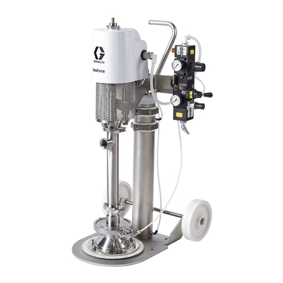
- Page 1 Operation SaniForce™ SaniForce™ SaniForce™ 3A5400B Pail Unloader Unloader System System Pail Pail Unloader System For use use with with with food food food grade grade bulk grade bulk bulk supply supply of of of medium supply medium medium to to to high high high viscosity viscosity product.
-
Page 2: Table Of Contents
Locate the Pump System......6 Grounding ........... 7 Dimensions ............12 Fluid Outlet Line........... 7 Technical Data ........... 13 Operation ............8 Graco Standard Warranty........14 Pressure Relief Procedure......8 Flush the Pump Before First Use ....8 Models Models Models... -
Page 3: Warnings
Warnings Warnings Warnings Warnings The following warnings are for the setup, use, grounding, maintenance, and repair of this equipment. The exclamation point symbol alerts you to a general warning and the hazard symbols refer to procedure-specific risks. When these symbols appear in the body of this manual or on warning labels, refer back to these Warnings. - Page 4 Warnings WARNING MOVING PARTS PARTS HAZARD HAZARD MOVING MOVING PARTS HAZARD Moving parts can pinch or amputate fingers and other body parts. • Keep clear of moving parts. • Do not operate equipment with protective guards or covers removed. • Pressurized equipment can start without warning. Before checking, moving, or servicing Pressure Relief Relief Procedure Procedure and disconnect all power sources.
-
Page 5: Configuration Matrix
Configuration Matrix Configuration Matrix Matrix Configuration Configuration Matrix Check the identification plate (ID) for the following matrix to define the components of your Configuration Number of your pump. Use the system. SPU A01AAA1AA0C21 A01AAA1AA0C21 A01AAA1AA0C21 Sample Configuration Configuration Number: Number: Sample Sample Configuration... -
Page 6: Installation
Installation Installation Installation Installation General Information Information General General Information The Typical Installation shown is only a guide for selecting and installing system components. Reference letters in the text, for example (A), refer to the callouts in the figures. The Pail Unloader System consists of parts which are stationary and parts attached to the air cylinder piston rod. -
Page 7: Grounding
Installation Integrated Integrated Integrated Air Air Control Control Control Second bleed-type bleed-type air air valve valve (W): (W): isolates air line • Second Second bleed-type valve (W): accessories and supply system for servicing. Locate upstream from all other air line accessories. The integrated air control includes: Air relief relief valve... -
Page 8: Operation
Operation Operation Operation Operation 2. Place a full pail on the base and center it under the Platen (D). 3. Adjust the pail to be sure it is aligned with the platen, and open the platen bleed port (J). NOTE: NOTE: NOTE: If the platen is not aligned properly for Pressure Relief... -
Page 9: Change Pail
Operation Change Pail Pail Change Change Pail 3. Remove the empty pail. 4. Inspect platen and, if necessary, remove 1. Turn off pump air supply by pushing the air motor any remaining material or material slider valve (BH) to the off position. build-up. -
Page 10: Maintenance
Maintenance Maintenance Maintenance Maintenance Lubrication Lubrication Lubrication • Flush at the lowest pressure possible. Check connectors for leaks and tighten as necessary. The pump is lubricated at the factory. It is designed • Flush with a fluid that is compatible with the fluid to require no further lubrication for the life of the being dispensed and the equipment wetted parts. -
Page 11: Cleaning The Platen
Maintenance Cleaning the the Platen Platen Cleaning Cleaning Platen 1. Remove the pail. See Change Pail, page 9 2. Lower the ram so that the platen is resting flat against the baseplate. 3. Disconnect the blowoff air hose at the blowoff port (K). -
Page 12: Dimensions
Dimensions Dimensions Dimensions Dimensions In. (mm) In. (mm) In. (mm) In. (mm) In. (mm) In. (mm) In. (mm) 62.82 (1596) 42.34 (1075) 6.0 (152) 24.82 (630) 12.0 (305) 22.0 (559) 10.0 (254) 3A5400B Springer Pumps, LLC Tel: 866-777-6060 Website: www.springerpumps.com Fax: 866-777-6383 Int'l: +001 267 404 2910... -
Page 13: Technical Data
Technical Data Technical Technical Technical Data Data Data Sanitary Pail Pail Unloader Unloader Sanitary Sanitary Pail Unloader Metric Metric Metric Maximum fluid working pressure 650 psi 4.5 MPa, 44.8 bar Maximum air inlet pressure 100 psi 0.7 MPa, 6.9 bar Air consumption See pump manual Maximum recommended pump... -
Page 14: Graco Standard Warranty
Graco to be defective. This warranty applies only when the equipment is installed, operated and maintained in accordance with Graco’s written recommendations. This warranty does not cover, and Graco shall not be liable for general wear and tear, or any malfunction, damage or wear caused by faulty installation, misapplication, abrasion, corrosion, inadequate or improper maintenance, negligence, accident, tampering, or substitution of non-Graco component parts.
Need help?
Do you have a question about the SaniForce SPU.A01AAA1AA0C21 and is the answer not in the manual?
Questions and answers