Innova IN-8012 Instruction And Safety Manual
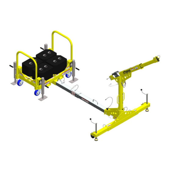
T-shaped universal base system for xtirpa universal rescue system vehicles and counterbalanced trucks
Hide thumbs
Also See for IN-8012:
- Instruction and safety manual (28 pages) ,
- Instruction and safety manual (40 pages)
Advertisement
Quick Links
INSTRUCTION AND SAFETY MANUAL FOR
T-SHAPED UNIVERSAL BASE SYSTEM FOR XTIRPA
VEHICLES AND COUNTERBALANCED TRUCKS
TO BE READ AND UNDERSTOOD BY USER PRIOR TO EACH USE
MU8012-012ENG rev05
UNIVERSAL RESCUE SYSTEM
IN-8012
INNOVA Public Utility Products Inc.
1040 Boulevard Industriel, Granby, Québec, Canada
Tel (450) 777-1240 Fax (450) 372-9936 www.xtirpa.com
Advertisement

Subscribe to Our Youtube Channel
Related Manuals for Innova IN-8012


Summary of Contents for Innova IN-8012
- Page 1 T-SHAPED UNIVERSAL BASE SYSTEM FOR XTIRPA VEHICLES AND COUNTERBALANCED TRUCKS UNIVERSAL RESCUE SYSTEM IN-8012 TO BE READ AND UNDERSTOOD BY USER PRIOR TO EACH USE INNOVA Public Utility Products Inc. 1040 Boulevard Industriel, Granby, Québec, Canada Tel (450) 777-1240 Fax (450) 372-9936 www.xtirpa.com MU8012-012ENG rev05...
- Page 2 EC DECLARATION OF CONFORMITY (English) Manufacturer established in the community: Produits de Services Publics INNOVA inc., 1040, boul. Industriel, Granby, Québec, Canada J2J 1A4 Declares that the following PPE product: IN-8012 XTIRPA Universal T-base system for 102mm (4") mast for PPE...
- Page 3 XTIRPA system waiving all claims, rights and recourses against the manufacturer derived therefrom. The XTIRPA IN-8012 universal safety system, including the following components: IN-2240 MU8012-012ENG rev05...
- Page 4 (Mast for fall protection and retrieval); IN-2313 (102mm (4’’) Mast for Davit-Arm IN-2237 1524mm (60’’) height); IN-2426 (Mast for davit arm 30’’ to 48’’ 500mm (19.7) high); IN-2237 (Extendable davit arm for fall protection and retrieval); IN-2305 (T-shaped universal base for 102mm (4”) mast);...
- Page 5 APPLICATION The XTIRPA system, and its many components and parts (including davit arm, manhole guard, removable adapter, permanent adapter, integrated mast and side entry cart), are intended to be used as part of a personal protection equipment system for fall protection, work positioning, per- sonnel handling, materials handling, or rescue, for use in confined spaces.
- Page 6 WARNING: The equipment should only be used by trained and competent persons to ensure safe use of this product. g) Always work in teams of at least two (2) people: 1 attendant and 1 confined space work- er (the person attached to the lifeline cable or rope). These people must be qualified and trained on the XTIRPA system.
- Page 7 XTIRPA system on a soft surface, including, but not limited to, sand, grass, gravel and rocks. If you have any questions about use or maintenance or whether the XTIRPA system is appropriate for your job, please contact the Manufacturer PSP INNOVA INC. MU8012-012ENG rev05...
- Page 8 WARNING: For safety reasons, make sure when using the anti-drop system that you have enough space under the user, so as to avoid injury. If a fall occurs, there should be enough space to avoid a collision with the ground or any obstacle. See the diagram in Section 8 for calculating this distance.
- Page 9 IMPORTANT: If you have questions on the use, care or suitability of the XTIRPA system for your application, please contact the manufacturer INNOVA Public Utility Products Inc. IMPORTANT: Record the product identification information from the ID label in the main- tenance and inspection log of this instruction and safety manual.
- Page 10 IMPORTANT: When used, the expandable coupling system for XTIRPA vehicles and counterbalanced trucks must be lifted using the adjustable supporting legs. The transport wheels must not be in contact with the ground. g) A person who has not read the Instruction and safety manual, has not been trained in using the XTIRPA system and does not understand all operation and safety instructions, is not qualified to operate the XTIRPA system.
- Page 11 WARNING: It is essential for the safety of the user, if the product is resold outside the first country of destination, that the reseller provides the user manual, the instructions for maintenance, for the periodic examinations as well as the instructions relating to repairs, written in the language of the country in which the product is used.
- Page 12 MAINTENANCE, SERVICING, STORAGE a) Before each use, the user must read and understand the Manufacturer’s Instruction and safety manual. Ensure that the markings are visible at all times. b) Before each use, carefully inspect the XTIRPA system and all components and parts there- of.
-
Page 13: Warranty
WARRANTY The XTIRPA system offered by the Manufacturer, INNOVA Public Utility Products Inc., is war- ranted against manufacturing defects in workmanship and materials for a period of two (2) years from the date of shipment of the product, which warranty only covers the original purchaser of the XTIRPA system. - Page 14 PORT ASSEMBLY (A2305-65): IN-8012 (see illustration 13) T-SHAPED UNIVERSAL BASE SYSTEM FOR VEHICLES AND 1829MM (72”) EXTENSION FOR 63.5MM(2.5”) T-SHAPED BASE COUPLING (A2305-16): IN-8012 (see illustration 14) T-SHAPED UNIVERSAL BASE SYSTEM FOR VEHICLES AND ADAPTOR 90-DEGREE EXTENSION (A2305-29): IN-8012 (see illustration 15) 63.5-51MM(2.5-2”) COUPLING REDUCER FOR T-SHAPED BASE EXTENSION: A2305-...
- Page 15 Illustration 1: IN- Illustration 4: Illustration 8: 2237 A2305-40 A2305-65 Illustration 2: IN- Illustration 9: Illustration 5: 2240 A2305-16 A2305-07 Illustration 10: Illustration 6: A2305-29 A2305-25 Illustration 3: IN- 2305 Illustration 11: IN-8012 Illustration 7: with A2305-07 A2305-12 MU8012-012ENG rev05...
- Page 16 Illustration 20: Illustration 12: Illustration 16: IN-2426 IN-8012 A2305-20 with A2305-12 Illustration 13: Illustration 17: IN-8012 A2305-55 Illustration 21: with A2305-65 IN-2525 Illustration 18: Illustration 14: Illustration 22: IN-2517 IN-8012 A2305-90 with A2305-16 Illustration 19: IN-2313 Illustration 15: IN-8012 with A2305-29...
- Page 17 TYPE A MOUNTING COMPATIBILITY ↓Typical composition↓ IN-2313 IN-2240 IN-2426 IN-2237 IN-2305 Assembly with A2305-12 TYPE B MOUNTING COMPATIBILITY ↓Typical composition↓ Assembly with A2305-20 A2305-20 A2305-25 A2305-55 A2305-16 MU8012-012ENG rev05...
- Page 18 Assembly with A2305-20 A2305-20 A2305-25 A2305-55 A2305-29 Installation with IN-2517 IN-2517 A2305-25 A2305-55 A2305-16 Installation with IN-2517 IN-2517 A2305-25 A2305-55 A2305-29 MU8012-012ENG rev05...
- Page 19 TYPE E MOUNTING COMPATIBILITY ↓Typical composition↓ IN-2313 IN-2240 IN-2426 IN-2237 IN-2305 Assembly with A2305-07 A2305-07 A2305-40 MU8012-012ENG rev05...
- Page 20 Installation with IN-2525 A2305-40 ↓Typical composition (continued)↓ IN-2313 IN-2240 IN-2426 IN-2237 IN-2305 Assembly with A2305-90 A2305-40 MU8012-012ENG rev05...
- Page 21 Assembly with A2305-65 A2305-40 MU8012-012ENG rev05...
- Page 22 IMPORTANT: If you have questions on the use, care or suitability of the XTIRPA system for your application, please contact the manufacturer INNOVA Public Utility Products Inc. IMPORTANT: Record the product identification information from the ID label in the main- tenance and inspection log of this instruction and safety manual.
- Page 23 Remove the pins from the leveling cylinders and rotate the latter to the vertical position. Adjust the leveling cylinders. Use the level bubble and make sure that it is in the center of the indicator dial. WARNING: When in use, it is imperative that the counterweight cart is lifted so that the wheels are not in contact with the ground, only the leveling cylinders.
- Page 24 Make sure the locking handle is securely screwed in place. Level the system. OPERATION AND INSTALLATION OF THE T-BASED SYSTEM WITH THE COUNTER- WEIGHT TROLLEY (IN-2525) Make sure that all components and pieces are in perfect working condition and that everything is functioning correctly.
- Page 25 WARNING: When used, the counterbalanced truck must be lifted so that the wheels do not come into contact with the ground, only the level adjustment screws. Insert extension tube and lock with pin. Insert extension tube into T-shaped universal base. Lock tube with pin.
- Page 26 Determine the location of the cart. Remove the pins from the legs to adjust the leveling of the car- riage. Use the level bubble and make sure that it is in the center of the indicator dial. Insert the extension tube and lock with the pin. Insert the extension tube into the universal base for T-mast.
- Page 27 Level the system. OPERATION AND INSTALLATION OF T-SHAPED BASE SYSTEM WITH BALLAST (A2305- Make sure that all components and pieces are in perfect working condition and that everything is functioning correctly. A. Assemble the two parts of the tank platform. B.
- Page 28 Lock the angle with the pin. OPERATION AND INSTALLATION OF T-SHAPED BASE SYSTEM FOR BALLAST SUP- PORT ASSEMBLY (A2305-65) (cont.) Insert the first part of the extension tube (A2305-40) into the adaptor on the platform and lock with the pin. Add the second part of the extension tube (A2305-40) to the first and lock with the pin.
- Page 29 OPERATION AND INSTALLATION OF T-SHAPED BASE WITH ANCHORING ADAPTOR FOR T-SHAPED UNIVERSAL BASE (A2305-12) Make sure that all components and parts are in perfect working condition and that they are all functioning properly. Insert anchoring adaptor for T-shaped universal base (A2305- 12) into T-shaped universal base.
- Page 30 Assemble the 1829mm (72”) extension for 63.5mm(2.5”) T-shaped base coupling (A2305- 16) to T-shaped base union with 1829mm (72”) extension (A2305-25) and lock with the pin. Assemble the 1829mm (72”) extension for 63.5mm (2.5”) T-shaped base coupling (A2305- 16) with 63.5-51mm(2.5-2”) coupling reducer for T-shaped base (A2305-20) and lock with pin.
- Page 31 Lock tube with pin. Make sure that the locking handle is frimly screwed in place. Level the system. OPERATION AND INSTALLATION OF T-SHAPED UNIVERSAL BASE SYSTEM WITH 90-DEGREE EXTENSION ADAPTOR (A2305-29) Make sure that all components and parts are in perfect working condition and that they are all functioning properly.
- Page 32 Installation of A2305-55 (if necessary). Insert 63.5- 51mm coupling reducer (2.5-2”) for T-shaped base extension (A2305-20) into vehicle hitch and lock with coupling pin. If necessary, insert vehicle coupling adapter (A2305-55) into previously installed A2305-20 and lock with pin. Insert 90 degree extension (A2305-29) into previously installed A2305-55 and lock with pin.
- Page 33 If necessary, adjust base length using existing holes. Adjust to the desired length and lock the two sides to the univer- sal T-shaped base with mast using locking pins. Stabilize the system using the adjustable support legs. When raising, make sure that the wheels do not touch the ground, only the adjustable support legs.
- Page 34 Install davit arm receptacle on mast. Lock with pin. Install lifeline or winch on the davit arm bracket designed for this type of equipment. Use provided locking pin on the lifeline or winch bracket and lock everything with it. A second lifeline or winch can be installed on the jib. Install the lifeline or additional winch on the support of the jib designed to receive this type of equipment.
- Page 35 If you have any questions about the use or maintenance or whether the XTIRPA system is appropriate for your job, please contact the Manufacturer PSP INNOVA INC. WARNING: Any system must be immediately removed from circulation if its safety is ques- tioned, or if it was used to stop a fall.
- Page 36 WARNING: For all fall protection devices, it is essential, for safety purposes, that anchor- ing device is always positioned correctly and that the task to be performed should be done in a manner to reduce risk of fall and height of fall. The anchoring point and fall protection device must be placed directly over the user’s position.
- Page 37 KEEP THE FOLLOWING INSTRUCTIONAL AND SAFETY SIGNS CLEAN AND LE- GIBLE AT ALL TIME SERIAL NUMBER LABEL Product serial number Product number Manufacturing date Manufacturing batch number CE ACCREDITATION LABEL Accredited standard’s no. EN 795:2012 Type A S2337-003 revD Product standard CE ACCREDITATION LABEL Notified body’s no.
- Page 38 CE ACCREDITATION LABEL Notified body’s no. Accredited standard’s no. 2754 EN 795:2012 Type E S2305-007 revC Product standard European compliance MU8012-012ENG rev05...
-
Page 39: Ground Clearance
CALCULATION DIAGRAM Ground Clearance: Length of the lanyard carabiner Extended length of the absorber Distance between harness buckle and feet = 4.9’ (1.5 m) Minimum safe distance = 3.3’ (1 m) Pay attention to the distance to the ground! MU8012-012ENG rev05... - Page 40 MU8012-012ENG rev05...
- Page 41 MU8012-012ENG rev05...
- Page 42 NOTES MU8012-012ENG rev05...
- Page 44 Head Office and Manufacturing Plant Innova Public Utility Productions Inc. 1040, Boulevard Industriel Canada, Qc, Canada J2J 1A4 Phone: 450.777.1240 Toll free: 1.800.461.1937 Xtirpa is a registered trademark of Innova Public Utility Productions Inc. used under www.xtirpa.com license in Canada MU8012-012ENG rev05...
Need help?
Do you have a question about the IN-8012 and is the answer not in the manual?
Questions and answers