Table of Contents
Advertisement
Quick Links
www.ti.com
User's Guide
Using the UCC14240EVM-052 for Biasing Traction Inverter
Gate Driver ICs Requiring Single, Positive or Dual,
Positive/Negative Bias Power
This user's guide provides a description and directions for the use of the UCC14240EVM-052 to evaluate the
UCC14240-Q1, high frequency, integrated transformer, DC-DC converter module from Texas Instruments. This
EVM allows designers to quickly and efficiently evaluate the UCC14240-Q1 for use in automotive or industrial
applications requiring gate driver IC bias power, meeting up to 3 kVRMS isolation.
1
Introduction.............................................................................................................................................................................2
1.1 Pin Configuration and Functions........................................................................................................................................
2 Description..............................................................................................................................................................................
2.1 EVM Electrical Performance Specifications.......................................................................................................................
3
Schematic................................................................................................................................................................................6
Operation......................................................................................................................................................7
4.1
Reference...........................................................................................................................................................................7
4.2 External Connections for Easy Evaluation.........................................................................................................................
4.3 Powering the EVM.............................................................................................................................................................
Points...............................................................................................................................................................10
5 Performance Data ................................................................................................................................................................
5.1 Efficiency Data.................................................................................................................................................................
5.2 Regulation Data...............................................................................................................................................................
5.3 Start-up Waveforms.........................................................................................................................................................
5.4 Inrush Current..................................................................................................................................................................
5.5 AC Ripple Voltage............................................................................................................................................................
5.6 EN and /PG Timing..........................................................................................................................................................
5.7 Shutdown.........................................................................................................................................................................
State.....................................................................................................................................................................21
5.9 Thermal Performance......................................................................................................................................................
(BOM)..........................................................................................................................................................27
8 Revision History...................................................................................................................................................................
Trademarks
All trademarks are the property of their respective owners.
SLUUCJ2 - JULY 2021
Submit Document Feedback
ABSTRACT
Table of Contents
EVM............................................................................................................................11
Layers...........................................................................................................23
Using the UCC14240EVM-052 for Biasing Traction Inverter Gate Driver ICs
Copyright © 2021 Texas Instruments Incorporated
Requiring Single, Positive or Dual, Positive/Negative Bias Power
Table of Contents
3
4
5
7
8
12
12
14
15
17
18
19
20
22
28
1
Advertisement
Table of Contents

Related Manuals for Texas Instruments UCC14240EVM-052


Summary of Contents for Texas Instruments UCC14240EVM-052
-
Page 1: Table Of Contents
Positive/Negative Bias Power ABSTRACT This user’s guide provides a description and directions for the use of the UCC14240EVM-052 to evaluate the UCC14240-Q1, high frequency, integrated transformer, DC-DC converter module from Texas Instruments. This EVM allows designers to quickly and efficiently evaluate the UCC14240-Q1 for use in automotive or industrial applications requiring gate driver IC bias power, meeting up to 3 kVRMS isolation. -
Page 2: Introduction
(PCB) area as well as a much lower height profile when compared to industry standards for power isolation techniques used in the field today. Using the UCC14240EVM-052 for Biasing Traction Inverter Gate Driver ICs SLUUCJ2 – JULY 2021... -
Page 3: Pin Configuration And Functions
VEEA pin. 1. P = power, G = ground, I = input, O = output SLUUCJ2 – JULY 2021 Using the UCC14240EVM-052 for Biasing Traction Inverter Gate Driver ICs Submit Document Feedback Requiring Single, Positive or Dual, Positive/Negative Bias Power... -
Page 4: Description
2 Description The UCC14240EVM-052 is intended to allow designers to evaluate the performance characteristics and capabilities of the UCC14240-Q1 quickly and easily for use in automotive, isolated, gate driver bias applications as well as a variety of isolated industrial bias power applications. The EVM allows users to test functions of the UCC14240-Q1 such as: Enable/Disable (ENA) of the device as well as configure the isolated output voltage for 15 V<VDD<20 V, and -5 V<VEE<0 V and easily apply variable loads to the outputs. -
Page 5: Evm Electrical Performance Specifications
1. Switching frequency is measured at VDD, VEE secondary and is 2x primary switching frequency SLUUCJ2 – JULY 2021 Using the UCC14240EVM-052 for Biasing Traction Inverter Gate Driver ICs Submit Document Feedback Requiring Single, Positive or Dual, Positive/Negative Bias Power... -
Page 6: Schematic
0.1% GNDP GNDP GNDP Figure 3-1. UCC14240EVM-052 Schematic Diagram Using the UCC14240EVM-052 for Biasing Traction Inverter Gate Driver ICs SLUUCJ2 – JULY 2021 Requiring Single, Positive or Dual, Positive/Negative Bias Power Submit Document Feedback Copyright © 2021 Texas Instruments Incorporated... -
Page 7: Evm Setup And Operation
Thermal camera (optional) or thermocouple to measure U1 case temperature 4.2 External Connections for Easy Evaluation The UCC14240EVM-052 EVM uses screw terminals for quickly connecting to the VIN, VDD ,and VEE pins. Connect the appropriate ammeters and voltmeters, as shown in... -
Page 8: Powering The Evm
VDD, 10V/div), time = 10ms/div unless otherwise noted. Figure 4-3. RC Debounce Filter, J3 PCB Bottom, R=5.11 kΩ, C=100 nF Using the UCC14240EVM-052 for Biasing Traction Inverter Gate Driver ICs SLUUCJ2 – JULY 2021 Requiring Single, Positive or Dual, Positive/Negative Bias Power Submit Document Feedback Copyright ©... - Page 9 10. Insert oscilloscope probes into TP10, TP6 and TP4 for measuring VIN, VDD and VEE start-up, steady state and AC ripple voltage SLUUCJ2 – JULY 2021 Using the UCC14240EVM-052 for Biasing Traction Inverter Gate Driver ICs Submit Document Feedback Requiring Single, Positive or Dual, Positive/Negative Bias Power...
-
Page 10: Evm Test Points
VIN, scope probe point TP11 Black GNDP, shared primary GND test point Using the UCC14240EVM-052 for Biasing Traction Inverter Gate Driver ICs SLUUCJ2 – JULY 2021 Requiring Single, Positive or Dual, Positive/Negative Bias Power Submit Document Feedback Copyright © 2021 Texas Instruments Incorporated... -
Page 11: Oscilloscope Probes: Probing The Evm
VDD and VEE to inadvertently drop out of regulation during light-load operation. SLUUCJ2 – JULY 2021 Using the UCC14240EVM-052 for Biasing Traction Inverter Gate Driver ICs Submit Document Feedback Requiring Single, Positive or Dual, Positive/Negative Bias Power... -
Page 12: Performance Data
21.01 199.68 19.16 130.13 14.34 -5.06 4.20 2.49 59.42 Using the UCC14240EVM-052 for Biasing Traction Inverter Gate Driver ICs SLUUCJ2 – JULY 2021 Requiring Single, Positive or Dual, Positive/Negative Bias Power Submit Document Feedback Copyright © 2021 Texas Instruments Incorporated... - Page 13 27.01 209.62 18.79 160.38 13.72 -5.07 5.66 3.01 53.23 SLUUCJ2 – JULY 2021 Using the UCC14240EVM-052 for Biasing Traction Inverter Gate Driver ICs Submit Document Feedback Requiring Single, Positive or Dual, Positive/Negative Bias Power Copyright © 2021 Texas Instruments Incorporated...
-
Page 14: Regulation Data
Figure 5-2. UCC14240EVM Regulation vs Power, VISO Loading Only Figure 5-3. UCC14240EVM Regulation vs Current, VISO Loading Only Using the UCC14240EVM-052 for Biasing Traction Inverter Gate Driver ICs SLUUCJ2 – JULY 2021 Requiring Single, Positive or Dual, Positive/Negative Bias Power Submit Document Feedback Copyright ©... -
Page 15: Start-Up Waveforms
Figure 5-5. Start-up 2: VIN=24 V, IISO=80 mA, (top: VISO, 10V/div, mid-1: COM, 5V/div, mid-2: VDD=VISO- COM, 10V/div, bot: VEE=-COM, 5V/div), time = 2ms/div unless otherwise noted. SLUUCJ2 – JULY 2021 Using the UCC14240EVM-052 for Biasing Traction Inverter Gate Driver ICs Submit Document Feedback Requiring Single, Positive or Dual, Positive/Negative Bias Power... - Page 16 Figure 5-7. Start-up 4: VIN=24 V, IISO=80 mA, (top: VISO, 10V/div, bot: COM, 2V/div), time = 2ms/div unless otherwise noted. Using the UCC14240EVM-052 for Biasing Traction Inverter Gate Driver ICs SLUUCJ2 – JULY 2021 Requiring Single, Positive or Dual, Positive/Negative Bias Power Submit Document Feedback Copyright ©...
-
Page 17: Inrush Current
IIN, 0.1A/div, mid-3: /PG, 5V/div, mid-4: VISO, 6.2V/div, 305µs/div, bot: IIN, 0.05A/div, 305µs/div), time = 2ms/div unless otherwise noted. SLUUCJ2 – JULY 2021 Using the UCC14240EVM-052 for Biasing Traction Inverter Gate Driver ICs Submit Document Feedback Requiring Single, Positive or Dual, Positive/Negative Bias Power... -
Page 18: Ac Ripple Voltage
Figure 5-11. AC Ripple: VIN=24V, IVDD=80 mA, IVEE=10 mA, FSW(pri)=12.9 MHz, (top: VISO, 0.1V/div, mid-1: COM, 0.02V/div, mid-2: COM, 0.02V/divc, 100ns/div, bot: VISO, 5mV/div, 100ns/div), time = 5µs/div unless otherwise noted. Using the UCC14240EVM-052 for Biasing Traction Inverter Gate Driver ICs SLUUCJ2 – JULY 2021 Requiring Single, Positive or Dual, Positive/Negative Bias Power Submit Document Feedback Copyright ©... -
Page 19: And
Figure 5-13. ENA to /PG Delay, 4.2 ms, IVDD=80 mA, (top: ENA, 5V/div, mid: /PG, 5V/div, bot: VDD, 10V/ div), time = 2ms/div unless otherwise noted. SLUUCJ2 – JULY 2021 Using the UCC14240EVM-052 for Biasing Traction Inverter Gate Driver ICs Submit Document Feedback Requiring Single, Positive or Dual, Positive/Negative Bias Power... -
Page 20: Shutdown
Figure 5-15. Shutdown EN Low: VIN=24 V, IVDD=80 mA, (top: VISO, 10V/div, mid-1: COM, 2V/div, mid-2: VDD=VISO-COM, 10V/div, mid-3: VEE=-COM, 5V/div, mid-4: /PG, 5V/div, bot: ENA, 5V/div), time = 2ms/div unless otherwise noted. Using the UCC14240EVM-052 for Biasing Traction Inverter Gate Driver ICs SLUUCJ2 – JULY 2021 Requiring Single, Positive or Dual, Positive/Negative Bias Power Submit Document Feedback Copyright ©... -
Page 21: Steady State
VISO1-VISO2, 20V/div, mid-3: -VISO2, 5V/div, mod-4: IIN, 0.2A/div, bot: VIN, 20V/div), time = 2ms/div unless otherwise noted. SLUUCJ2 – JULY 2021 Using the UCC14240EVM-052 for Biasing Traction Inverter Gate Driver ICs Submit Document Feedback Requiring Single, Positive or Dual, Positive/Negative Bias Power... -
Page 22: Thermal Performance
RISE Figure 5-18. Rated Power = 60.5°C − 25°C = 35.5°C RISE Using the UCC14240EVM-052 for Biasing Traction Inverter Gate Driver ICs SLUUCJ2 – JULY 2021 Requiring Single, Positive or Dual, Positive/Negative Bias Power Submit Document Feedback Copyright © 2021 Texas Instruments Incorporated... -
Page 23: Assembly And Printed Circuit Board (Pcb) Layers
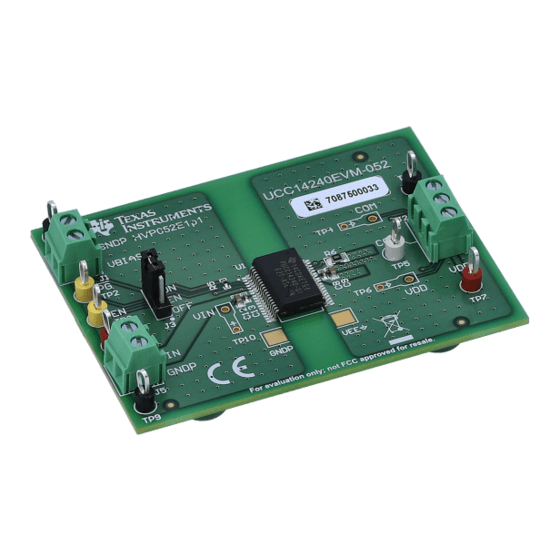
Assembly and Printed Circuit Board (PCB) Layers 6 Assembly and Printed Circuit Board (PCB) Layers The UCC14240EVM-052 is designed using a four-layer PCB. The EVM, PCB demonstrates the important use of ground planes and stitching vias for shielding and improving EMI performance. For higher density PCBs... - Page 24 Figure 6-2. UCC14240EVM-052, Fully Assembled 3D Bottom View Figure 6-3. UCC14240EVM-052, 3D Angle View Using the UCC14240EVM-052 for Biasing Traction Inverter Gate Driver ICs SLUUCJ2 – JULY 2021 Requiring Single, Positive or Dual, Positive/Negative Bias Power Submit Document Feedback...
- Page 25 Assembly and Printed Circuit Board (PCB) Layers Figure 6-4. UCC14240EVM-052, PCB Top Layer, Assembly Figure 6-5. UCC14240EVM-052, Signal Layer 2 (same as layer 3) SLUUCJ2 – JULY 2021 Using the UCC14240EVM-052 for Biasing Traction Inverter Gate Driver ICs Submit Document Feedback Requiring Single, Positive or Dual, Positive/Negative Bias Power Copyright ©...
- Page 26 Assembly and Printed Circuit Board (PCB) Layers www.ti.com Figure 6-6. UCC14240EVM-052, Signal Layer 3 (same as layer 2) Figure 6-7. UCC14240EVM-052, PCB Bottom Layer, Assembly (mirrored view) Using the UCC14240EVM-052 for Biasing Traction Inverter Gate Driver ICs SLUUCJ2 – JULY 2021...
-
Page 27: Bill Of Materials (Bom)
TP1, TP9, TP11 Black Test Point, 5011 Keystone Multipurpose, Black SLUUCJ2 – JULY 2021 Using the UCC14240EVM-052 for Biasing Traction Inverter Gate Driver ICs Submit Document Feedback Requiring Single, Positive or Dual, Positive/Negative Bias Power Copyright © 2021 Texas Instruments Incorporated... -
Page 28: Revision History
NOTE: Page numbers for previous revisions may differ from page numbers in the current version. DATE REVISION NOTES Initial Release Using the UCC14240EVM-052 for Biasing Traction Inverter Gate Driver ICs SLUUCJ2 – JULY 2021 Requiring Single, Positive or Dual, Positive/Negative Bias Power Submit Document Feedback Copyright © 2021 Texas Instruments Incorporated... - Page 29 TI products. TI’s provision of these resources does not expand or otherwise alter TI’s applicable warranties or warranty disclaimers for TI products.IMPORTANT NOTICE Mailing Address: Texas Instruments, Post Office Box 655303, Dallas, Texas 75265 Copyright © 2021, Texas Instruments Incorporated...
Need help?
Do you have a question about the UCC14240EVM-052 and is the answer not in the manual?
Questions and answers