Sign In
Upload
Manuals
Brands
Texas Instruments Manuals
Controller
UCC14240EVM-052
Texas Instruments UCC14240EVM-052 Board Manuals
Manuals and User Guides for Texas Instruments UCC14240EVM-052 Board. We have
2
Texas Instruments UCC14240EVM-052 Board manuals available for free PDF download: User Manual
Texas Instruments UCC14240EVM-052 User Manual (37 pages)
for Biasing Traction Inverter Gate Driver ICs Requiring Single, Positive or Dual, Positive/Negative Bias Power
Brand:
Texas Instruments
| Category:
Motherboard
| Size: 2 MB
Table of Contents
Table of Contents
1
Introduction
3
U1 Component Selection
3
Pin Configuration and Functions
3
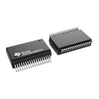
Figure 1-1. DWN Package, 36-Pin SSOP
3
Table 1-1. Ucc1424X-Q1 Version Differences
3
Table 1-2. Pin Functions
4
Description
5
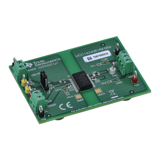
Figure 2-1. UCC14240EVM-052, HVP052A, Top View
5
Figure 2-2. UCC14240EVM-052, HVP052A, Bottom View
5
EVM Electrical Performance Specifications
6
Table 2-1. EVM Electrical Specifications
6
Schematic
7
Figure 3-1. UCC14240EVM-052 Schematic Diagram
7
EVM Setup and Operation
8
Recommended Test Equipment
8
External Connections for Easy Evaluation
8
Figure 4-1. Typical Efficiency Measurement
8
Powering the EVM
9
EVM Test Points
10
Table 4-1. Input, Output, Test Point (I/O/TP) Description
10
Probing the EVM
11
Figure 4-2. UCC14240EVM-052, PCB Scope Probe Test Points
11
Performance Data
12
Efficiency Data
12
Figure 5-1. Measured Efficiency, VDD-VEE Loading Only
12
Table 5-1. Efficiency Test Data (VIN = 21 V)
12
Table 5-2. Efficiency Test Data (VIN = 24 V)
13
Table 5-3. Efficiency Test Data (VIN = 27 V)
13
Regulation Data
14
Figure 5-2. Regulation Vs Power, VDD-VEE Loading Only
14
Figure 5-3. Regulation Vs Current, VDD-VEE Loading Only
14
IVDD-Vee
14
Steady State Input Current
15
Start-Up Waveforms
15
Figure 5-4. Input Current Vs Power, VDD-VEE Loading Only
15
Figure 5-5. Start-Up 1: VIN=24 V, I
15
Figure 5-6. Start-Up 2: VIN=24 V, I
16
Figure 5-7. Start-Up 3: VIN=24 V, I
16
VDD-VEE = 80 Ma
16
Inrush Current
17
Figure 5-8. Start-Up 4: VIN=24 V, IISO
17
Figure 5-9. Inrush Current: VIN=24 V, I
17
AC Ripple Voltage
18
Figure 5-10. Inrush Current: VIN=24 V, I
18
Figure 5-11. VDD AC =300 MV, VEE AC =108 MV, IVDD =80 Ma, IVEE =10 Ma
18
Figure 5-12. AC Ripple: VIN=24 V, IVDD=80 Ma, IVEE=10 Ma, FSSM = 5 Khz
19
Figure 5-13. AC Ripple: VIN=24 V, IVDD=80 Ma, IVEE=10 Ma, FMOD=45 Khz
19
Figure 5-14. AC Ripple: VIN=24 V, IVDD=80 Ma, FSW(PRI)=12.95 Khz
20
Figure 5-15. AC Ripple: VIN=24 V, IVDD=80 Ma, FBURST=1 Mhz
20
Rlim
21
Figure 5-16. ENA to /PG Delay, 3.9 Ms, I
21
Figure 5-17. RLIM: VIN=24 V, I
21
Figure 5-18. RLIM: VIN=24 V, I
22
Figure 5-19. RLIM: VIN=24 V, I
22
Fault Protection
23
Figure 5-20. Output UVLO, PVDD=0 Mw, PVEE = 73 Mw
23
Figure 5-21. VEE OVP, VIN=24 V, PVDD=247 Mw, PVEE
24
Figure 5-22. Normal Start, VIN=24 V, PVDD=247 Mw, PVEE
24
Shutdown
25
Figure 5-23. Shutdown by VIN Removal: VIN
25
Figure 5-24. Shutdown by en Low: VIN=24 V, I
25
Thermal Performance
26
Figure 5-25. Steady State, PMAX =2 W
26
Figure 5-26. Rated Power, P=1.65 W
26
Assembly and Printed Circuit Board (PCB) Layers
27
Figure 6-1. UCC14240EVM-052, Fully Assembled 3D Top View
27
Figure 6-2. UCC14240EVM-052, Fully Assembled 3D Bottom View
27
Figure 6-3. UCC14240EVM-052, 3D Angle View
27
Figure 6-4. UCC14240EVM-052, PCB Top Layer, Assembly
28
Figure 6-5. UCC14240EVM-052, GND Layer 2 (same as Layer 3)
28
Figure 6-6. UCC14240EVM-052, GND Layer 3 (same as Layer 2)
29
Figure 6-7. UCC14240EVM-052, PCB Bottom Layer, Assembly (Mirrored View)
29
Bill of Materials (BOM)
30
Table 7-1. UCC14240EVM-052 BOM
30
Revision History
31
Advertisement
Texas Instruments UCC14240EVM-052 User Manual (29 pages)
Using the UCC14240EVM-052 for Biasing Traction Inverter Gate Driver ICs Requiring Single, Positive or Dual, Positive/Negative Bias Power
Brand:
Texas Instruments
| Category:
Controller
| Size: 3 MB
Table of Contents
Table of Contents
1
1 Introduction
2
Pin Configuration and Functions
3
2 Description
4
EVM Electrical Performance Specifications
5
3 Schematic
6
4 EVM Setup and Operation
7
Reference
7
External Connections for Easy Evaluation
7
Powering the EVM
8
EVM Test Points
10
Oscilloscope Probes: Probing the EVM
11
5 Performance Data
12
Efficiency Data
12
Regulation Data
14
Start-Up Waveforms
15
Inrush Current
17
AC Ripple Voltage
18
And
19
Shutdown
20
Steady State
21
Thermal Performance
22
6 Assembly and Printed Circuit Board (PCB) Layers
23
7 Bill of Materials (BOM)
27
8 Revision History
28
Advertisement
Related Products
Texas Instruments UCC38500EVM
Texas Instruments UCD90320
Texas Instruments UCC14240-Q1
Texas Instruments UCC14141EVM-068
Texas Instruments UCC14131EVM-070
Texas Instruments UCC14341EVM-069
Texas Instruments UCC14141-Q1
Texas Instruments UCC2977EVM
Texas Instruments UCC27425-Q1
Texas Instruments UCC25640EVM-020
Texas Instruments Categories
Motherboard
Control Unit
Microcontrollers
Computer Hardware
Calculator
More Texas Instruments Manuals
Login
Sign In
OR
Sign in with Facebook
Sign in with Google
Upload manual
Upload from disk
Upload from URL