AKCP SPX+ Introduction Manual
Hide thumbs
Also See for SPX+:
- Security features manual (24 pages) ,
- Manual (7 pages) ,
- Quick start manual (9 pages)
Table of Contents
Advertisement
Advertisement
Table of Contents

Related Manuals for AKCP SPX+


Summary of Contents for AKCP SPX+
- Page 1 SPX+ Introduction Manual Copyright © 2019, AKCP...
-
Page 2: Table Of Contents
SPX+ Introduction Manual - updated until firmware 4997 Table of Contents Introduction ..............................4 Specifications ........................... 7 SPX+ Modules ..........................8 Expansion architecture ..........................11 Port assignment information for SPX+ units ..................... 12 LED information for SPX+ units ........................13 Reset button functions for SPX+ units ....................... - Page 3 SPX+ Introduction Manual - updated until firmware 4997 VPN ............................47 Set up VPN connection to APS................48 SMTP ............................ 52 SNMP ............................ 54 Server Integration ....................... 56 Services ..........................57 SSL Certificate......................58 Modbus ..........................61 Password Checking and security ..................62 Password Security options ...................
-
Page 4: Introduction
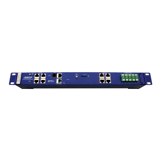
1U, 0U and DIN rail mounting with a low profile design it takes up much less cabinet space. SPX+ comes in several standard configurations, but with the AKCP configuration tool you are able to custom design a unit to your own specifications. Choose from various modules to specify the number of dry contacts, sensor ports or an internal modem. - Page 5 Please see the section in this manual on how to setup a new IP address on the unit. C) AKCP also always highly recommends using a dedicated 3rd party UPS on the units. Any damage caused by unstable power or power outages will void the warranty on our units.
- Page 6 SPX+ Introduction Manual - updated until firmware 4997 In the SP+ units web UI you will be able to view which platform the unit is using. This can be checked in the Settings >> General page >> System Description: And in the Settings >> About page >> System Description: - 6 -...
-
Page 7: Specifications
(Non-Condensing) MTBF: 1,400,000 Hours based on field experience with sensorProbe units. Base Unit: 4x Sensor Ports for connecting AKCP sensors or swing handle cabinet locks, 1x Expansion Out Port (Optionally used for Modbus), 1x BEB port, 1x 10/100 Ethernet Port... -
Page 8: Spx+ Modules
Additional sensor ports can be added to the base SPX+ module in blocks of 4. The sensor4 modules are compatible with all AKCP intelligent sensors. Build a cost effective monitoring platform, able to monitor multiple cabinets from a single IP address. - Page 9 This module is ideal for connecting third party analogue sensors with a 0-5VDC scale output. Many industrial sensors are available with this scale output, opening up the possibilities of monitoring many different sensors not provided by AKCP. 4x Mini Relays This module includes 4x mini DC relays.
- Page 10 SPX+ Introduction Manual - updated until firmware 4997 Ball Valve Control Module If you have DC motors or electronically controlled ball valves which require polarity reversal to turn in the opposite direction, this module is applicable. Ideal for water irrigation or industrial applications which require valve and motor controls.
-
Page 11: Expansion Architecture
SPX+ Introduction Manual - updated until firmware 4997 Expansion Architecture Every SPX+ comes with both EXP (Expansion) and BEB (Basic Expansion Bus) ports. These expansion ports give you the ability to add functionality to your base device, so your system can grow with your needs. -
Page 12: Port Assignment Information For Spx+ Units
Connect additional remote BEB units, or E-Sensor8 / E-Opto16 expansion units to increase the capabilities and number of sensors your SPX+ can monitor. Important: On the expansion port you cannot connect AKCP sensors; it’s only for the expansion units. Cellular modem For remote site locations, or those places without a WAN network connection an internal 3G/4G GSM modem can be installed to give 24/7 connectivity. -
Page 13: Led Information For Spx+ Units
SPX+ Introduction Manual - updated until firmware 4997 LED information for SPX+ units Reset Eth/Exp Buzzer Sensor LEDs Power LED Dry Contact LEDs The Ethernet/Expansion LEDs have standard indication LEDs for network activity and connection state (green and orange). The Power LED is red, simply on or off. Sensor LEDs (red) and Dry Contact LEDs (green) can have different states: Off = offline On = online and normal... -
Page 14: Reset Button Functions For Spx+ Units
SPX+ Introduction Manual - updated until firmware 4997 Reset button functions for SPX+ units There are specific commands you can send to the unit by holding the Reset button for a specified amount of time. You’ll have to use something sharp, such as a straightened paperclip to be able to press Reset. Commands: Time to hold Action <... -
Page 15: Setting Up The Unit's Ip Address
SPX+ Introduction Manual - updated until firmware 4997 Setting up the unit’s IP address Very Important Note: The unit’s ship with the passwords enabled. The default log in for the web interface is Username: admin Password: public Every unit is shipped with the default IP address of 192.168.0.100 First we will go through the process of changing this IP address to fit your own network configuration. - Page 16 SPX+ Introduction Manual - updated until firmware 4997 How to add a manual route to the computer’s routing table? Open an Administrator Command Prompt (CMD) window and type: route add 192.168.0.100 10.1.1.20 Where 10.1.1.20 is the IP address of the Ethernet interface on the PC that the unit is plugged into with the crossover cable.
-
Page 17: Spx+ Web Ui Walkthrough
Important Note:- As Microsoft no longer supports the Internet Explorer web browser, we also do not support any version of IE when viewing our web interface on all AKCP base units. Please use the Chrome or Firefox browsers when viewing the base units web UI. -
Page 18: Monitoring Summary Page
SPX+ Introduction Manual - updated until firmware 4997 Monitoring Summary page This is the Summary page with Sensor Status and the Event Log, with the Temperature Sensor Graph enabled. Host Log The Host Log contains all entries from the “All Events” category. We’ll explain the different categories in the Notifications manual. - Page 19 SPX+ Introduction Manual - updated until firmware 4997 In the Summary page’s Sensors Information window you can do the following: Click on the configuration menu button directly next to the right of a sensor to access its popup menu. Directly acknowledge a sensor’s status, and put the sensor offline Control the relay-type sensors Enable/disable graph data collection per sensor (if they support it), and display the graph display window for the Summary page...
-
Page 20: Graph Feature
SPX+ Introduction Manual - updated until firmware 4997 Graph feature After you’ve enabled the data collection for a sensor, you can choose to display specific time intervals of the stored data: hourly/daily/weekly/monthly and custom display interval. You can also export the recorded data in multiple formats. Important: The maximum number of enabled graphs per unit is 14. - Page 21 SPX+ Introduction Manual - updated until firmware 4997 The graph is always a Live Graph; you can set the data collection period in the General Settings page (see below for more information). You may also refresh the graph data manually with the refresh button on the right. If you want to view multiple sensor graphs, first you need to Enable Graph for a sensor that supports graphing from the sensor’s menu.
-
Page 22: Expansion Units
SPX+ Introduction Manual - updated until firmware 4997 Expansion Units If you have an expansion unit connected and sensors on the expansion board, they will be also listed in the System Name Information window as shown below. If you have a BEB unit, please refer to that separate manual titled SPX+ BEB Units. -
Page 23: Managing Desktops And Maps
SPX+ Introduction Manual - updated until firmware 4997 Managing Desktops and Maps The updated SP+ Web UI has the Workspaces feature from the AKCPro Server’s HTML5 UI. With this you can manage and view different Desktop layouts in a quick and easy way, create multiple custom Desktops as well as select from pre-defined layouts with placeholders for displaying your sensor gauges, logs etc. -
Page 24: Important Notes On Custom Desktops
SPX+ Introduction Manual - updated until firmware 4997 Important Notes on custom desktops Please note the custom Desktops that are created ARE NOT stored in the SP+ units memory. These are HTML based, so they are stored in the browser cache, or local data on the Chrome & Firefox browsers. -
Page 25: Managing Desktops
SPX+ Introduction Manual - updated until firmware 4997 Managing Desktops Navigation You can manually change between Desktops using the arrow menu, or by directly clicking on the desired Desktop if they are stacked under a folder. With this button, your current Desktop will expand to the browser’s screen width as shown on the screenshot below: Click it again to go back to the full view. - Page 26 SPX+ Introduction Manual - updated until firmware 4997 On each Desktop and Folder item, you have the option to Rename, Move, Export or Delete them. Move is useful if you’ve created multiple folders (see below). As noted earlier, don’t forget to export your Workspace items to save them permanently. - 26 -...
-
Page 27: Folders
SPX+ Introduction Manual - updated until firmware 4997 Folders You can add Folders to arrange your desktops into a hierarchical view. After created, you can simply drag and drop your Desktops under the folder, or use the Move menu. The folder structure will also display on the Desktop selector menu on top: - 27 -... -
Page 28: Desktops
SPX+ Introduction Manual - updated until firmware 4997 Desktops You can add new Desktops where you can customize the layout to place any sensor gadget, logs, graphs etc. on the screen. There are two ways to add a new desktop. The first is by creating a blank desktop using the Add Desktop link under the Workspace tab: Name the new desktop and click the Add button. - Page 29 SPX+ Introduction Manual - updated until firmware 4997 In addition to the simple blank desktop, the second way to add a new desktop is via pre-defined Desktop Layouts. You could choose one that best suits your monitoring needs to drag and drop your sensor gadgets.
- Page 30 SPX+ Introduction Manual - updated until firmware 4997 The empty desktop will have placeholders similar to this: As an example below, we’ve selected the 1+1+2 layout. Then you can drag and drop sensors, logs and graphs on the layout: Below we’ll show you how you can add sensors to the desktops. - 30 -...
-
Page 31: Adding Items To Your Custom Desktop
To add items from the units that are connected to the SP+ unit, you will first need to click on the AKCP link in the Navigation Tree as shown above. Next simply drag and drop the items you wish to add to your new desktop. This is also how you can add items to the Summary page. -
Page 32: Desktop Auto Scroll Feature
SPX+ Introduction Manual - updated until firmware 4997 Desktop Auto Scroll feature With this feature enabled, your desktop view will automatically switch between the created additional desktops within the specified time interval. You can also manually change between Desktops using the menu. - 32 -... -
Page 33: Managing Rack Maps
SPX+ Introduction Manual - updated until firmware 4997 Managing Rack Maps The Rack Map feature was originally (and still is) included in the AKCess Pro Server / AKCPro Server (HTML5) and has also been added to the SP+ units. You can add a Rack Map as a graphical representation of your server rack, and to display and record the temperature of the airflow within your server cabinets. - Page 34 SPX+ Introduction Manual - updated until firmware 4997 You can add Temperature sensors, the Swing Handle Lock and the Sensor Status Light gadget on a Rack Map. Simply drag and drop the desired sensor from your unit’s sensor list, as shown below. This example picture shows a Sensor Status Light added to a Rack Map.
-
Page 35: Access Control Users And Groups
SPX+ Introduction Manual - updated until firmware 4997 Access Control Users and Groups The Access Control Users and Groups are managed from the AKCPro Server and are used for accessing doors with the Swing Handle Lock. You can only view the existing users and groups from the unit’s Web UI and modify only a few parameters on them. -
Page 36: Notifications And Events, Sensors Menu, Settings Menu
SPX+ Introduction Manual - updated until firmware 4997 Notifications and Events You can view all of the SP+ unit’s events and filter them by each of the categories’ listed above in the Events drop down menu. Please refer to the SP+ units “Notifications Manual” for setting up the alerts and the Event log on the units. -
Page 37: System Page
SPX+ Introduction Manual - updated until firmware 4997 System page General Here you can change general settings for the device. The unit’s firmware version is shown in the Description field, and the System Name/Location/Contact options are user configurable. You could also specify the System URL option, for quick access of a custom part of the Web UI for example, but you can specify any URL. - Page 38 SPX+ Introduction Manual - updated until firmware 4997 With the option Sensor Notification On System Boot Up, you can choose to allow/disallow running the notifications with sensor values read at system boot up. In some cases, invalid values are read while the unit is starting up, and you could get false alarm notifications.
-
Page 39: Language Management
SPX+ Introduction Manual - updated until firmware 4997 Language management You can change the display language of the Web UI with this option. Only one additional language is supported, together with the default (and fallback if there’s an error) English. In Manage, you can choose to Download Language File if you’d like to edit the language file offline (you can also download the custom language’s file if it’s already present). - Page 40 SPX+ Introduction Manual - updated until firmware 4997 You can get separately downloadable language files from our website in the Support section. If you have active internet connection, the unit supports installing the official language files directly from our server. Select a language from the drop-down menu Install New Language: Then press the Install button.
- Page 41 SPX+ Introduction Manual - updated until firmware 4997 The unit will notify you about the successful language installation. If you installed it from the list, it won’t change the language of the Web UI automatically. Now you can switch display languages by selecting from the drop-down list on the General page, then pressing Save: After you’ve added the custom language, you can manage it from the same menu: Note: The official language files are also included in the firmware update packages.
- Page 42 SPX+ Introduction Manual - updated until firmware 4997 You can also edit the chosen language directly in the Web UI, if you choose Edit Language: - 42 -...
-
Page 43: Date/Time
SPX+ Introduction Manual - updated until firmware 4997 Date/Time The system date and time with time zone is user configurable, with NTP server synchronization. If the unit is connected to APS (AKCPro Server), then it will sync with the APS NTP service. Also displayed is the status of the RTC battery (good/bad). -
Page 44: Network
SPX+ Introduction Manual - updated until firmware 4997 Network The unit’s MAC ID is displayed here, and all user configurable options for IPv4 with fixed IP or DHCP client mode. F7 units also have IPv6 settings (separately licensed feature), we have a separate manual about this feature. -
Page 45: Modem
SPX+ Introduction Manual - updated until firmware 4997 Modem If the unit is equipped with the internal modem module, then the modem’s Dial-Out configuration can be set up here for data connections. Contact your service provider for the correct settings. You can also see on this page the state of the connection, the Network Mode and the assigned IP address when connected, if the SIM card is detected properly by the modem (SIM Status), and the Signal Level. - Page 46 SPX+ Introduction Manual - updated until firmware 4997 You may select a different Connection Mode (PAP/GPRS/RAS). The most commonly used is GPRS Unsecured. You may change the Connection Method as follows: Never Dial Out (Use Ethernet only): the unit will never try to use the modem for sending out notifications.
-
Page 47: Vpn
SPX+ Introduction Manual - updated until firmware 4997 This feature requires a separate license. You can read more details about the licensing later in this manual. This feature is used by connecting the SP+ with the APS VPN server. After the license has been activated and the APS VPN server is set up, you’ll need to fill out the same options here to be able to use the VPN connection (see below). -
Page 48: Set Up Vpn Connection To Aps
SPX+ Introduction Manual - updated until firmware 4997 Set up VPN connection to APS In the following pages, we’ll describe how to set up the VPN connection to APS. 1. On APS HTML, Go to Settings>Server Settings>Virtual Private Network Enable the VPN Server by clicking on the checkbox, and then change the Network Password in Authentication Setting. - Page 49 SPX+ Introduction Manual - updated until firmware 4997 You could also configure the VPN settings using the deprecated APS Windows Client interface: Settings>Server Option>Virtual Private Network - 49 -...
- Page 50 SPX+ Introduction Manual - updated until firmware 4997 2. On the SP+ Web UI, enable the VPN First change the VPN Client on the top to "Enabled" and configure the VPN Settings on the form: - Specify the AKCPro Server's IP or DNS name in VPN Server Address - Use the VPN Network Password that you have specified on APS - Set up the the VPN Encrypt Method on the Encryption tab;...
- Page 51 SPX+ Introduction Manual - updated until firmware 4997 3. On your APS console, the SP+ unit will be added to the Server Explorer automatically, with an IP address automatically assigned from the range you specified. Important notes: A) If the SP+ was previously added to the APS using a LAN IP, it has to be removed (delete host).
-
Page 52: Smtp
SPX+ Introduction Manual - updated until firmware 4997 SMTP The SMTP server configuration options are shown here, it’s required to be set up for the Email actions. Fill out all parameters; the address in the Email From parameter will be used by the Email actions by default, but you could change it if your mail server supports it (when it’s not required to match the SMTP user for example). - Page 53 SPX+ Introduction Manual - updated until firmware 4997 Settings for Gmail You can use Gmail account to send Email alerts with the settings shown on this screenshot on the left. Important: before this can work, you’ll need to set up an additional setting in your Google account. Open Gmail in a web browser and go to Settings / Accounts and Import / Other Google Account settings...
-
Page 54: Snmp
SPX+ Introduction Manual - updated until firmware 4997 SNMP The SNMP service configuration options are shown here, it is required for SNMP operations. SNMPv1 is enabled by default, with community password “public”. This is provided for the easiest integration with third party SNMP tools. For enhanced security, it is recommended that you change the default SNMP password. - Page 55 SPX+ Introduction Manual - updated until firmware 4997 SNMPv3 The SNMPv3 options can be found by scrolling down on the SNMP page. This feature requires a separate license. You can read more details about the licensing below in this manual. Below we’ll give a quick description of each setting: Level Authentication...
-
Page 56: Server Integration
SPX+ Introduction Manual - updated until firmware 4997 Server Integration If the unit has been added to the AKCPro Server console, the server’s IP address will be displayed here. User configurable options are the APS port and keep-alive period. You can change the APS port when the server’s port changes, and the keep-alive period (heartbeat sync to APS). -
Page 57: Services
SPX+ Introduction Manual - updated until firmware 4997 Services You can close or change the ports used to access the unit’s web interface, disable HTTP and enable HTTPS only, which can also be set to be used as default. On the SP+ family, the HTTPS supports TLS v1.1 and v1.2. The HTTPS cypher suites are not customizable. -
Page 58: Ssl Certificate
SPX+ Introduction Manual - updated until firmware 4997 SSL Certificate SSL certificates are generated for DNS host names and not IP addresses. You should set a host name for the SP+ unit in your local DNS server or DHCP server, and then generate the SSL certificate for that host name. - Page 59 SPX+ Introduction Manual - updated until firmware 4997 The .PEM file is the private key + certificate combined. You can copy them to one file using Notepad++ if you have 2 separate files, as shown below (it has to be in Unix Line Format and not Windows): - 59 -...
- Page 60 SPX+ Introduction Manual - updated until firmware 4997 If you don’t upload a certificate but enable HTTPS, a built-in certificate will be used. You’ll get a browser warning upon opening the Web UI about an incorrect certificate. This is normal and you should add it as an exception or proceed, depending on your browser: Important: the default, built-in self-signed SSL certificate is only provided for user convenience so that the HTTPS WebUI would work on the units out of the box.
-
Page 61: Modbus
Note: Modbus queries are slow (up to 3 seconds). This is per Modbus protocol definition, it’s not an AKCP limitation. The more sensors you have, the bigger the polling interval must be. Configuring the Modbus options and more information about this feature is explained in the separate SP+ Modbus manual. -
Page 62: Password Checking And Security
SPX+ Introduction Manual - updated until firmware 4997 Password Checking and Security You can turn on the password checking for the Web UI to ensure only authenticated users have access to the unit. You can also specify to show all user names on the login page, or keep them confidential. -
Page 63: Password Security Options
SPX+ Introduction Manual - updated until firmware 4997 Password Security options All user account types (Admin, User, Viewer) have adjustable password expiration and lockdown periods. The password can be up to 15 characters (a-z, A-Z, 0-9 and special characters). The IP address of the remote user’s computer will be logged in the syslog so you can trace back each login session to its origin. - Page 64 SPX+ Introduction Manual - updated until firmware 4997 Lockdown The accounts can be set to lock down the account after 3 invalid login attempts, to prevent brute-force hacking attempts. You can specify how long the account will automatically unlock itself. Note that for the Admin user, you can’t select “indefinitely”...
- Page 65 SPX+ Introduction Manual - updated until firmware 4997 Password Expiration You can specify password expiration between every 15 and 90 days for all account types. You could also set “none” to disable expiration. You’ll get a notification upon login when the password has expired, and will be asked to change it. It’s advised to change it when asked, but you can still proceed without changing.
-
Page 66: Maintenance
SPX+ Introduction Manual - updated until firmware 4997 Maintenance On this page the following options are available: Clear Event Logs: clears all logged events. Restore Original Settings: removes all customized settings and returns the unit to factory defaults - you can also choose to keep the network configuration intact. Backup/Restore All Settings: the unit’s configuration can be backed up to a file and restored quickly and easily. - Page 67 SPX+ Introduction Manual - updated until firmware 4997 System Firmware Upgrade: allows you to upgrade to the latest firmware of the unit - alternatively you could upgrade from APS. We’ll show you the process of the Web UI firmware upgrade below in another section.
-
Page 68: Heartbeat Messages
SPX+ Introduction Manual - updated until firmware 4997 Heartbeat Messages This feature allows you to set up periodical “keep alive” notifications task by email, SMS or SNMP Trap to indicate the unit is still working properly. We’ll show you how to set up these in another manual with the other notifications and actions. - 68 -... -
Page 69: License Management
SPX+ Introduction Manual - updated until firmware 4997 License Management Here you can manage the purchased licenses for specific features on the unit. For example you can request SNMPv3 license by clicking on the Request License button. This will send an email to our Sales team with your unit’s MAC ID. You can then add the purchased license key with the Add button and activate this feature on the unit. - Page 70 SPX+ Introduction Manual - updated until firmware 4997 Features that needs separate licensing: 5 Dry Contact option: Allows you to connect 5 dry contacts (input only) per sensor ports. See below for more information. Access Control User licenses over 100: The first 100 user licenses are free (1 is always used for the Admin user), and you can get more licensed users in blocks of 100;...
-
Page 71: About
SPX+ Introduction Manual - updated until firmware 4997 About This page shows information about the Manufacturing Date, Ethernet MAC ID, System Description and unit type (F4/F7) which are important when you request support. If equipped, the internal modem’s details will be also listed here. You could make a similar screenshot when you need help with your unit, as this information can help us diagnose the problem. -
Page 72: Sensors Page
SPX+ Introduction Manual - updated until firmware 4997 Sensors page On this page you can view all sensors connected to the unit per port, and per board. Non-connected sensors will be also displayed, until you re-attach or manually remove them from the configuration. - Page 73 SPX+ Introduction Manual - updated until firmware 4997 You could modify a connected board by clicking on the pencil icon: From here you can rename any board, and disable a disconnected expansion board. The SPX+ units can have extra Dry Contact boards attached. We’ll describe more about the Dry Contacts below in another section of this manual;...
-
Page 74: General Options For All Sensors
SPX+ Introduction Manual - updated until firmware 4997 General options for all sensors You can change the following general options for all sensors: Disable Auto Sense Click on the Auto Sense button to turn off the automatic sensor detection for a port. This feature is useful if you want to simulate a sensor (this works for Relay type sensors) or to prevent a sensor from going offline state. - Page 75 SPX+ Introduction Manual - updated until firmware 4997 Offline a sensor You can manually offline any sensor by clicking on the green Online button on the sensor’s configuration page. You’ll be asked for confirmation in a popup window. Note: if you change a sensor to “offline” it will no longer be displayed on the web interface. In order to reactivate it, you have to toggle it back to “online”.
- Page 76 SPX+ Introduction Manual - updated until firmware 4997 Change Continuous Time The following advanced functions are for setting the time frame in which the system should delay a notification being triggered when a sensor gives a reading that exceeds the thresholds (high warning, normal, etc).
-
Page 77: Virtual Sensors
SPX+ Introduction Manual - updated until firmware 4997 Virtual Sensors On this page you can configure the Virtual Sensors. The first 5 sensors are free; if you need to use more you can purchase additional licenses (see the Licensing section in this manual). Virtual Sensors can be a very powerful tool in your monitoring system. - Page 78 SPX+ Introduction Manual - updated until firmware 4997 SNMP Get, sensor logic evaluation and ping commands among others are all possible from the virtual sensors. An example use of this could be to use the SPX+ as a probe manager. If you had a SPX+ and multiple sensorProbe devices they could all be monitored, mapped and alerted via the SPX+.
-
Page 79: Dry Contact Sensors
SPX+ Introduction Manual - updated until firmware 4997 Dry Contact Sensors With the user definable Dry Contact Sensor you can monitor a variety of devices and alarm panels with Dry Contact inputs, such as UPS status, security systems, air conditioning status, burglar alarms, fire alarms or any application that requires monitoring by the sensorProbe+. -
Page 80: Connecting To The Dry Contacts
Configuring the Dry Contact Sensor Since all of AKCP’s intelligent sensors are configured similarly, not every field is described below. The descriptions below describe the fields which are special to the Dry Contact sensor. The rest of the configuration is similar to the Relay Sensor (see below in this manual). - Page 81 SPX+ Introduction Manual - updated until firmware 4997 Description of Status When Normal: This field is the custom description, which will be displayed in the Status field when the dry contact sensor is Normal. Examples for this field are: Door Open, Pump Turned On, Light Turned On, etc. Description of Status When Critical: This field is the custom description, which will be displayed in the Status field when the dry contact sensor is Critical.
-
Page 82: Isolated Dry Contact Details
SPX+ Introduction Manual - updated until firmware 4997 Information on Dry Contact cables: The extension length of the Dry Contact twisted pairs is limited only by the amount of electromagnetic noise in the area. So the lengths can be quite long, but long cable lengths may create occasional false positives. -
Page 83: Dry Contact Module Types
SPX+ Introduction Manual - updated until firmware 4997 Dry Contact module types The optional 10 or 20 dry contact modules for the SPX+ units can be one of three types as follows:- 1. The I/O (input / output) 5VDC 2. The 5VDC opto coupled (non-isolated) input only - make sure you don’t exceed 5V or you can damage the unit! 3. -
Page 84: Example Sensor Configuration
SPX+ Introduction Manual - updated until firmware 4997 Example sensor configuration Below we’ll show the configuration of 2 sensor types: the Temperature/Humidity and a Relay sensor. The configuration of these 2 types of sensors covers most settings that can be configured for other sensor types. - Page 85 SPX+ Introduction Manual - updated until firmware 4997 You can re-configure the thresholds for each sensor state. After changing a threshold value, click “Save”. In the next screen shot you can see that a threshold has been changed to 27 make a new “low warning”...
- Page 86 SPX+ Introduction Manual - updated until firmware 4997 Advanced sensor configuration for Temperature/Humidity sensors Units: changes units from °C to °F or vice versa. Rearm: The Rearm parameter is useful for sensors whose values can vary such as the temperature and humidity sensors.
- Page 87 SPX+ Introduction Manual - updated until firmware 4997 Data Collection Type: This refers to the data collection from the sensor and how the data is then displayed on the graphs. There are four options for the collection of data: Average, Highest, Lowest and Instantaneous. The default setting is “Average”.
-
Page 88: Relay Sensor
SPX+ Introduction Manual - updated until firmware 4997 Relay Sensor Click on the sensor port where the sensor is connected to open the sensor’s configuration. Note: another way of accessing this page is to click on the sensor from the Summary page. You can directly see the Relay’s current status below the sensor port. - Page 89 SPX+ Introduction Manual - updated until firmware 4997 Advanced sensor configuration for Relay sensors Sensor Control: This button allows you to manually control the relay by controlling the cycle of the relay in an on-off- on or an off-on-off cycle. You can also set the “Toggle” (Cycle Time) here in seconds. You don’t need to change an option to be able to link the relay to an action.
- Page 90 SPX+ Introduction Manual - updated until firmware 4997 Enable Calendar: Allows you to setup a Calendar Profile for what days and times you want or do not want the relay to be active. Click on the Edit button next to a selected calendar to modify it. Blue cells means that the notification is on, white cells means it’s off.
- Page 91 SPX+ Introduction Manual - updated until firmware 4997 You can quickly select the Working Hours only, and specify a custom schedule down to minutes by right clicking on a cell. - 91 -...
-
Page 92: Pulse Counter Sensor
SPX+ Introduction Manual - updated until firmware 4997 Pulse Counter sensor The pulse counter is available on the SP+ platform, as of firmware version 1.0.4967. It provides: - accumulated pulse count - flow conversion of the pulse count It can measure up to 1000 pulses / sec (1 Kilohertz). Normally this sensor should be used with some external sensor which outputs pulses. - Page 93 SPX+ Introduction Manual - updated until firmware 4997 For example, you can connect the output of a third-party water flow sensor in the market to our sensor port. The specs of those sensors will indicate how many pulses equal to, for example 1 liter: 100 pulses = 1 Liter.
- Page 94 SPX+ Introduction Manual - updated until firmware 4997 In the Flow Sensor there is "Number of Pulse per Unit" in the config. You can use this value to adjust the sensor reading to match the real-world value. Dry contact will also work but only to count the pulses. If you want to test for the rate accuracy, you'd have to test with something that can generate a wave signal, like using an oscilloscope to generate wave form and plug it to the sensor port.
-
Page 95: Firmware Upgrade Through The Web Ui
SPX+ Introduction Manual - updated until firmware 4997 Firmware upgrade through the Web UI The firmware upgrade process is very simple and straight-forward. Open the System/Maintenance page and click on the Upgrade button at the System Firmware Upgrade section. This will load the Upgrade page. Choose the firmware file from your PC and click on Upgrade to start the process. - Page 96 SPX+ Introduction Manual - updated until firmware 4997 First the file will be uploaded to the unit… …then the upgrade process will run. The whole process can be done in a few minutes. The Power/Ethernet LED will be red during the upgrade. The unit will reboot at the end of the upgrade.
-
Page 97: Network Ports Used By Sp+ Units
SPX+ Introduction Manual - updated until firmware 4997 Network ports used by SP+ units Below we list the ports used by our SP+ units. Most of them are needed for external communications with APS, and to use network features. Most ports are user configurable, these are the default ports. Main ports: ... - Page 98 SPX+ Introduction Manual - updated until firmware 4997 Please contact support@akcp.com if you have any further technical questions or problems Thanks for Choosing AKCP! - 98 -...
Need help?
Do you have a question about the SPX+ and is the answer not in the manual?
Questions and answers