Table of Contents
Advertisement
Advertisement
Table of Contents

Related Manuals for AKCP SensorProbe2 PLUS


Summary of Contents for AKCP SensorProbe2 PLUS
- Page 1 SP2+ Introduction Manual Copyright © 2016, AKCP...
-
Page 2: Table Of Contents
SP2+ Introduction Manual Table of Contents Introduction ..............................3 Port assignment information for SP2+ units ....................4 LED information for SP2+ units ........................5 Reset button functions for SP2+ units......................6 Setting up the unit’s IP address ........................7 SP2+ Web UI Walkthrough ........................... 8 Summary page .......................... -
Page 3: Introduction
● Virtual Sensors ● Patented Fire Suppression feature ● AKCP Swing Handle Lock support Important note: Some of the pictures shown in this manual might not represent the actual Web UI of the unit; this is because we are constantly working on improving the firmware. Please provide us with feedback if you have any issues configuring your unit. -
Page 4: Port Assignment Information For Sp2+ Units
Port numbering starts from the power connector on the unit: the closest port to the power connector is Port 1 and closest to the Ethernet interface is Port 4. You may connect AKCP intelligent sensors to any available ports. Important note: If you're using analog pins on the sensor ports (with manually on-lined DCV sensors, and pin 7 of the RJ45 connector) make sure that the voltage doesn't exceed 3 Volts. -
Page 5: Led Information For Sp2+ Units
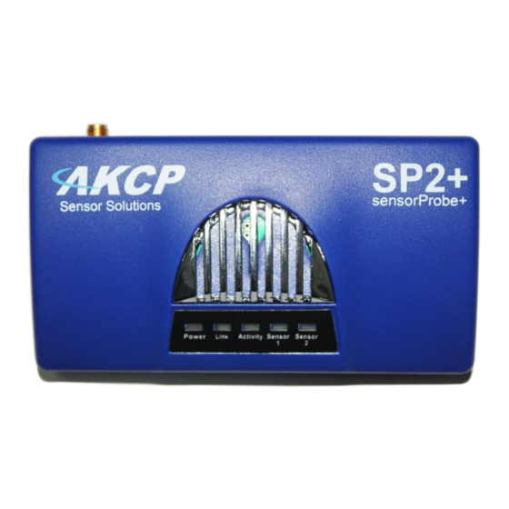
SP2+ Introduction Manual LED information for SP2+ units Power/Ethernet Link - Sensor 1 - Sensor 2 - Sensor 3 - Sensor 4 The Power/Ethernet LED will become red if there’s no network connection, and blinking green (according to LAN activity) when the connection is normal. For sensor LEDs (green): Off = offline On = online and normal... -
Page 6: Reset Button Functions For Sp2+ Units
SP2+ Introduction Manual Reset button functions for SP2+ units There are specific commands you can send to the unit by holding the Reset button for a specified amount of time. You’ll have to use something sharp, such as a straightened paperclip to be able to press Reset. Commands: Time to hold Action 3..7 sec... -
Page 7: Setting Up The Unit's Ip Address
SP2+ Introduction Manual Setting up the unit’s IP address Very Important Note: The unit’s ship with the passwords enabled. The default log in for the web interface is Username: admin Password: public Every unit is shipped with the default IP address of 192.168.0.100 First we will go through the process of changing this IP address to fit your own network configuration. - Page 8 SP2+ Introduction Manual How to add a manual route to the computer’s routing table? Open an Administrator Command Prompt (CMD) window and type: route add 192.168.0.100 10.1.1.20 Where 10.1.1.20 is the IP address of the Ethernet interface on the PC that the unit is plugged into with the crossover cable.
-
Page 9: Sp2+ Web Ui Walkthrough
SP2+ Introduction Manual SP2+ Web UI Walkthrough Menu navigation With newer firmware (after 1.0.3074), the Web UI and the menu structure has been changed on all SP+ family devices. To open the menu, click on the three horizontal lines in the upper left corner: - 9 -... - Page 10 SP2+ Introduction Manual This will bring up the full menu for navigation. Depending on the device, you might see additional menu items, such as Power. - 10 -...
-
Page 11: Summary Page
SP2+ Introduction Manual Summary page This is the Summary page with Sensor Status and the Event Log, with the Sensor Graph enabled. The Event Log contains all entries from the “All Events” category. We’ll explain the different categories in the Notifications manual. The last 30 entries are shown, but if you’re scrolling down the list, more events (30 more) will be loaded automatically. - Page 12 SP2+ Introduction Manual In the Summary page’s Sensors Information window you can do the following: Directly acknowledge a sensor’s status, and put the sensor offline Control the relay-type sensors Enable/disable graph data collection per sensor, and display the graph display window for the Summary page We’ll explain the Graph feature in more detail below.
-
Page 13: Graph Feature
SP2+ Introduction Manual Graph feature After you’ve enabled the data collection for a sensor, you can choose to display specific time intervals of the stored data: hourly/daily/weekly/monthly and custom display interval. You can also export the recorded data in multiple formats. In this example picture, we’ve chosen to display the temperature sensor’s daily maximum. - Page 14 SP2+ Introduction Manual By choosing the Live Graph option, you can get continuous update of the graph data (by default every 60 seconds). If you don’t use this option, the graph data needs to be refreshed manually. To change to a different sensor’s graph, choose it from the drop-down menu. Note that you could only choose a sensor here that you’ve already enabled the graph data collection for.
-
Page 15: System Page
SP2+ Introduction Manual System page General Here you can change general settings for the device. The unit’s firmware version is shown in the Description field, and the System Name/Location/Contact options are user configurable. You could also specify the System URL option, for quick access of a custom part of the Web UI for example, but you can specify any URL. - Page 16 SP2+ Introduction Manual With the option Sensor Notification On System Boot Up, you can choose to allow/disallow running the notifications with sensor values read at system boot up. In some cases, invalid values are read while the unit is starting up, and you could get false alarm notifications. You can disable the notification processing at startup with this option.
-
Page 17: General & Language
SP2+ Introduction Manual Language management You can change the display language of the Web UI with this option. Only one additional language is supported, together with the default (and fallback if there’s an error) English. In Manage, you can choose to Download Language File if you’d like to edit the language file offline (you can also download the custom language’s file if it’s already present). - Page 18 SP2+ Introduction Manual You can also edit the language directly in the Web UI, if you choose Edit Language: If the custom language file is present, you can select it from the drop-down list on the General page: - 18 -...
-
Page 19: Date/Time
SP2+ Introduction Manual Date/Time The system date and time with time zone is user configurable, with NTP server synchronization. If the unit is connected to APS (AKCess Pro Server), then it will sync with the APS NTP service. Also displayed is the status of the RTC battery (good/bad). You can also select the frequency of NTP synchronization with the drop-down menu. -
Page 20: Network
SP2+ Introduction Manual Network The unit’s MAC ID is displayed here, and all user configurable options for IPv4 with fixed IP or DHCP client mode. - 20 -... -
Page 21: Modem
SP2+ Introduction Manual Modem If the unit is equipped with the internal modem module, then the modem’s Dial-Out configuration can be set up here for data connections. Contact your service provider for the correct settings. You can also view the state of the connection and the assigned IP address when the connection is established. - Page 22 SP2+ Introduction Manual You may change the Connection Method as follows: Never Dial Out (Use Ethernet only): the unit will never try to use the modem for sending out notifications. If you don’t have Ethernet connection, you should change this setting; otherwise you won’t get any notifications.
-
Page 23: Vpn
SP2+ Introduction Manual This feature requires a separate license. You can read more details about the licensing later in this manual. This feature is used by connecting the SP2+ with the APS VPN server. After the license has been activated and the APS VPN server is set up, you’ll need to fill out the same options here to be able to use the VPN connection. -
Page 24: Smtp
SP2+ Introduction Manual SMTP The SMTP server configuration options are shown here, it’s required to be set up for the Email actions. Fill out all parameters; the address in the Email From parameter will be used by the Email actions by default, but you could change it if your mail server supports it (when it’s not required to match the SMTP user for example). - Page 25 SP2+ Introduction Manual SNMP The SNMP service configuration options are shown here, it is required for SNMP operations. SNMPv1 is enabled by default, with community password “public”. Scroll down for SNMPv3 options. - 25 -...
-
Page 26: Snmp & Snmpv3
SP2+ Introduction Manual SNMPv3 The SNMPv3 options can be found by scrolling down on the SNMP page. This feature requires a separate license. You can read more details about the licensing below in this manual. Below we’ll give a quick description of each setting: Level Authentication Encryption Description... -
Page 27: Server Integration
SP2+ Introduction Manual Server Integration If the unit has been added to the AKCess Pro Server console, the server’s IP address will be displayed here. User configurable options are the APS port and keep-alive period. You can change the APS port from the Web UI when the server’s port changes. Alternatively you can re-initialize your unit from the APS console to re-establish communication. -
Page 28: Password Checking
SP2+ Introduction Manual Password Checking Password checking for the Web UI can be turned on/off here, along with the option for specifying the password for the different user access levels. After you enable the password checking, you’ll need to re-login. If you don’t remember the admin password, you can hold the unit’s reset button for 7-12 seconds to be able to log in to the Web UI without a password. -
Page 29: Maintenance
SP2+ Introduction Manual Maintenance On this page the following options are available: Clear Event Logs: clears all logged events. Restore Original Settings: removes all customized settings and returns the unit to factory defaults - you can also choose to keep the network configuration intact. Backup/Restore All Settings: the unit’s configuration can be backed up to a file and restored quickly and easily. -
Page 30: Heartbeat Messages
SP2+ Introduction Manual Heartbeat Messages This feature allows you to set up periodical “keep alive” notifications task by email, SMS or SNMP Trap to indicate the unit is still working properly. We’ll show you how to set up these in another manual with the other notifications and actions. - 30 -... -
Page 31: License Management & About
SP2+ Introduction Manual License Management Here you can manage the purchased licenses for specific features on the unit. For example you can request SNMPv3 license by clicking on the Request License button. This will send an email to our Sales team with your unit’s MAC ID. You can then add the purchased license key with the Add button and activate this feature on the unit. - Page 32 SP2+ Introduction Manual Features that needs separate licensing: 5 Dry Contact option: Allows you to connect 5 dry contacts (input only) per sensor ports. See below for more information. Access Control User licenses over 100: The first 100 user licenses are free (1 is always used for the Admin user), and you can get more licensed users in blocks of 100;...
- Page 33 SP2+ Introduction Manual About This page shows information about the Manufacturing Date, Ethernet MAC ID, and System Description which are important when you request support. You could make a similar screenshot when you need help with your unit, as this information can help us diagnose the problem.
-
Page 34: Sensors Page
SP2+ Introduction Manual Sensors page On this page you can view all sensors connected to the unit per port. Non-connected sensors will be also displayed, until you re-attach or manually remove them from the configuration. You could also rename the unit’s Main board by clicking on the pencil icon: Please note the maximum supported cable length to use with Thermal Map Sensors: Maximum extension cable length from the SP2+ sensor port to the TMS using CAT5 = 28 Feet Maximum extension cable length from the SP2+ sensor port to the TMS using CAT5e &... -
Page 35: General Options For All Sensors
SP2+ Introduction Manual General options for all sensors You can change the following general options for all sensors: Disable Auto Sense Click on the Auto Sense button to turn off the automatic sensor detection for a port. This feature is useful if you want to simulate a sensor (this works for Relay type sensors) or to prevent a sensor from going offline state. - Page 36 SP2+ Introduction Manual Offline a sensor You can manually offline any sensor by clicking on the green Online button on the sensor’s configuration page. You’ll be asked for confirmation in a popup window. Note: if you change a sensor to “offline” it will no longer be displayed on the web interface. In order to reactivate it, you have to toggle it back to “online”.
- Page 37 SP2+ Introduction Manual Change Continuous Time The following advanced functions are for setting the time frame in which the system should delay a notification being triggered when a sensor gives a reading that exceeds the thresholds (high warning, normal, etc). Continuous Time to Report High Critical: This helps to eliminate unnecessary messages during minor fluctuations.
- Page 38 SP2+ Introduction Manual Virtual Sensors On this page you can configure the Virtual Sensors. The first 5 sensors are free, if you need to use more you can purchase additional licenses (see the Licensing section in this manual). Virtual Sensors can be a very powerful tool in your monitoring system. On the SP2+ you can have up to 50 of these virtual sensors and they allow for a multitude of applications.
-
Page 39: Example Sensor Configuration
SP2+ Introduction Manual Example sensor configuration Below we’ll show the configuration of 2 sensor types: the Temperature/Humidity and a Relay sensor. The configuration of these 2 types of sensors covers most settings that can be configured for other sensor types. Temperature/Humidity Sensor Click on the sensor port where the sensor is connected to open the sensor’s configuration. -
Page 40: Temperature/Humidity Sensor
SP2+ Introduction Manual You can re-configure the thresholds for each sensor state. After changing a threshold value, click “Save”. In the next screen shot you can see that a threshold has been changed to 27 make a new “low warning” state, and along with it the sensor status has changed: Note: the Humidity sensor has the same configuration options as the Temperature sensor. - Page 41 SP2+ Introduction Manual Advanced sensor configuration for Temperature/Humidity sensors Units: changes units from °C to °F or vice versa. Rearm: The Rearm parameter is useful for sensors whose values can vary such as the temperature and humidity sensors. It is used to prevent the sensor from rapidly changing between two states. For example if the Warning High threshold for the temperature sensor is set to 80 degrees and the sensor were to vary between 79 and 80 you could be faced with a very large number of emails, traps, and events logged.
- Page 42 SP2+ Introduction Manual Data Collection Type: This refers to the data collection from the sensor and how the data is then displayed on the graphs. There are four options for the collection of data: Average, Highest, Lowest and Instantaneous. The default setting is “Average”.
-
Page 43: Relay Sensor
SP2+ Introduction Manual Relay Sensor Click on the sensor port where the sensor is connected to open the sensor’s configuration. Note: another way of accessing this page is to click on the sensor from the Summary page. Description of Status When Relay Off: This field is the custom description, which will be displayed in the Relay Status field when the relay state is off. - Page 44 SP2+ Introduction Manual Advanced sensor configuration for Relay sensors Control Mode: 1. Manual Control allows you to manually control the relay using the “Sensor Control” option by controlling the cycle of the relay in an on-off-on or an off-on-off cycle. You can also set the “Toggle” (Cycle Time) here in seconds.
- Page 45 SP2+ Introduction Manual 3. Time Control: Allows you to setup a Calendar Profile for what days and times you want or do not want the relay to be active. Click on the Edit button next to a selected calendar to modify it. Blue cells means that the notification is on, white cells means it’s off.
- Page 46 SP2+ Introduction Manual You can quickly select the Working Hours only, and specify a custom schedule down to minutes by right clicking on a cell. - 46 -...
-
Page 47: Firmware Upgrade Through The Web Ui
SP2+ Introduction Manual Firmware upgrade through the Web UI The firmware upgrade process is very simple and straight-forward. Open the System/Maintenance page and click on the Upgrade button at the System Firmware Upgrade section. This will start the Upgrade page. Choose the firmware file from your PC and click on Upgrade to start the process. - Page 48 SP2+ Introduction Manual First the file will be uploaded to the unit… …then the upgrade process will run. The whole process can be done in a few minutes. The Power/Ethernet LED will be red during the upgrade. The unit will reboot at the end of the upgrade. Click on the Refresh button to reload the Web UI. - 48 -...
- Page 49 SP2+ Introduction Manual Please contact support@akcp.com if you have any further technical questions or problems Thanks for Choosing AKCP! - 49 -...
Need help?
Do you have a question about the SensorProbe2 PLUS and is the answer not in the manual?
Questions and answers