
Related Manuals for AKCP PMS120-CT50


Summary of Contents for AKCP PMS120-CT50
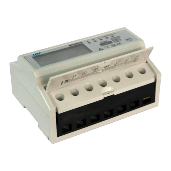
- Page 1 Power Monitor Sensor Three Phase & CT Type User Manual Help Version updated till firmware 404p Copyright © 2012, AKCess Pro Co., Ltd..
- Page 2 Three Phase and Three Phase CT Type PMSFL User Manual - 2 What is the Power Monitoring Sensor? The Power Monitoring Sensor or PMS as it will be referred to through the rest of this user manual for DIN rail Three Phase four wire and Three Phase CT Type multi-tariff energy meter with MODBUS protocol.
- Page 3 Three Phase and Three Phase CT Type PMSFL User Manual - 3 Do not connect while circuit is live (hot). Do not connect the meter to a 3 phase - 400VAC – network. Place or install the meter only in dry surroundings. ...
- Page 4 Three Phase and Three Phase CT Type PMSFL User Manual - 4 Meter specifications:...
-
Page 5: Very Important
Three Phase and Three Phase CT Type PMSFL User Manual - 5 Three Phase PMS Readings Each Three Phase PMS can be setup to monitor up to 14 separate values as follows; For a 3 phase the following values can be measured - 3 Voltages - 3 Amps - 3 Power Factor... - Page 6 Three Phase and Three Phase CT Type PMSFL User Manual - 6 Installing / Connecting the Meters We recommend that the connecting wire which is used to connect the meter to the outside circuit should be sized according to local codes and regulations for the amps of the circuit breaker or over current device used in the circuit.
-
Page 7: Connection Diagram
Three Phase and Three Phase CT Type PMSFL User Manual - 7 Connection Diagram 1/2 Ia IN/OUT 3/4 Ib IN/OUT 5/6 Ic IN/OUT 7 Neutral wire 8/12 Test pulse output contact (P+/P-) 9/12 Test pulse output contact (Q+/Q-) 10/11 RS485 communication contact (to securityProbe) CT –... - Page 8 Three Phase and Three Phase CT Type PMSFL User Manual - 8 pulse light, Phase A/B/C . The constant of the impulse is shown on the nameplate of the meter. Reading the meter The Three Phase PMS and CT-Type PMS is equipped with 6+2 LCD display. which is used as recording Active/Reactive consumption and can’t be reset to zero and other power Parameters include U/I/P/Q/S/PF.
- Page 9 Three Phase and Three Phase CT Type PMSFL User Manual - 9 Meter can display 32 items as above mentioned. The display time of every item is 5 seconds. You can only setup the CT after the meter is connected to electricity. If the“ ”disappeared on it means you cannot change the CT setting, when the “...
- Page 10 Three Phase and Three Phase CT Type PMSFL User Manual - 10 CT Type PMS - Changing-Ratio setting How to set the CT Changing- Ratio of the CT Type Meter Please set the CT Changing-Ratio after installation otherwise the CT Meter will count the second energy consumption by default Ratio ( 5:5).
- Page 11 Connect two wires/twisted pair from ports 9 and 10 to the terminal block on the securityProbe RS485 port. The AKCP PMS uses the Modbus connection (RS485) port on the rear of the securityProbe (note your rear panel may differ depending on the model of securityProbe you have) Using a pair of wires from ports 9 and10 on the PMS (see wiring diagram) to the terminal block on your securityProbes RS485 port.
- Page 12 - the two ends of the cable must be connected on Line Terminations. If you have any questions about this please consult with your engineer or contact us at support@akcp.com Adding each PMS to the securityProbe’s web interface When adding the multiple PMS to the web interface in the securityProbe base unit you have to add each PMS one at a time then change the ID from "1"...
- Page 13 Three Phase and Three Phase CT Type PMSFL User Manual - 13 PMS as ID 1. 2. Connect the second PMS, run the scan ID, set this PMS to ID 2, and then remove this PMS both physically and from the web interface. This will hard code the PMS as ID 2. 3.
- Page 14 Three Phase and Three Phase CT Type PMSFL User Manual - 14 This will now bring you to the "Scan Meter" page, follow the directions below for a quick setup:- Once the AC Power has been connected to the PMS and the meter has been connected to the units RS-485 port click on the “Start”...
- Page 15 Three Phase and Three Phase CT Type PMSFL User Manual - 15 You can also add the meter manually by clicking on the “Add Meter” button as shown in the screen shot above. The meters ID number will be from 1 to 256. You can also change a meters ID number using the “Change Meter ID”...
- Page 16 Three Phase and Three Phase CT Type PMSFL User Manual - 16 Once the scan has begun any connected PMS units will be detected and added and put online as shown in the screen shot above. You can enter your Scan range if you know the amount of meters you will be adding.You can stop the scan at any time by clicking on the “Stop”...
- Page 17 Three Phase and Three Phase CT Type PMSFL User Manual - 17 above. In the next screen you can enable all the values by adding a check in each of the check boxes that represent each of the listed values. Then you would click on the “Next” button to continue as shown in the screen shot above.
- Page 18 Three Phase and Three Phase CT Type PMSFL User Manual - 18 In the next screen you can setup your Polling Interval times and retry times as shown above. Polling Interval -Here you can select how often the securityProbe polls information from the PMS unit.
- Page 19 Three Phase and Three Phase CT Type PMSFL User Manual - 19 Now you are able setup each of the sensors or value thresholds as shown in the screen shot above. If you have the 3 phase PMS connected to each of the 3 phases of the AC lines each Phase Line will be shown in the PMS Menu column as shown in the screen shot above.
- Page 20 Three Phase and Three Phase CT Type PMSFL User Manual - 20 Replacement Procedures for previous type PMS with new type Please use the following steps if your replacing an old type PMS with this new type PMSFL in the same Modbus string. 1.
- Page 21 Question #2 How are the CT’s or Current Transformers assembled and how do I open them? Answer Please see the separate manual for the current transformers on this (down load this from your support page or request this from support@akcp.com...
- Page 22 Three Phase and Three Phase CT Type PMSFL User Manual - 22 Question #3 Can the PMS monitor the AC without the neutral? Answer No, can not Question #4 Can I connect the Modbus output directly to alternative BMS interface? Answer We use the Modbus RTU standard on RS485.
- Page 23 Three Phase and Three Phase CT Type PMSFL User Manual - 23 Question #7 What are the Modbus Read Regisors for the PMS? Answer Please see the registors on the follow page which includes the chart showing all the read registors.
- Page 24 Three Phase and Three Phase CT Type PMSFL User Manual - 24 Modbus Read Registers for the PMS This is the setting. Modbus-RTU on RS485 Baudrate: 9600 parity bit: even data bit: 8 stop bit: 1 See this table for the Modbus registers. Question #8 Do you know where I can get more informaton online about AC power and voltage? Yes, please go to this page on the web for more informaton;...
- Page 25 Three Phase and Three Phase CT Type PMSFL User Manual - 25 This concludes the PMS User Manual I you have any further questions or problems with the PMS please contact support@akcp.com for further assistance. Thanks for choosing AKCess Pro!
Need help?
Do you have a question about the PMS120-CT50 and is the answer not in the manual?
Questions and answers