Table of Contents
Advertisement
Quick Links
Advertisement
Table of Contents

Subscribe to Our Youtube Channel
Related Manuals for CZone Control X

Summary of Contents for CZone Control X
- Page 1 Control X User & Installation Manual V1.0...
- Page 2 EN / CZone® Control X User & Installation Manual Copyright This document is copyright 2018 under the Creative Commons agreement. Rights are granted to research and reproduce elements of this document for non-commercial purposes on the condition that BEP Marine is credited as the source.
-
Page 3: Table Of Contents
EN / CZone® Control X User & Installation Manual TABLE OF CONTENTS GENERAL INFORMATION Use Of This Manual Guarantee Specifications Quality Validity Of This Manual Liability Changes To The Control X SAFETY AND INSTALLATION PRECAUTIONS Warnings And Symbols Use For Intended Purpose... - Page 4 TABLE OF FIGURES Figure 1. Product Overview ........................8 Figure 2. LED Indicators .......................... 9 Figure 3. CZone Control X Capacitive Touch Pannel ................10 Figure 4. CZone Control X PLUS System Example................11 Figure 5. Deutsch HDT-48-00 Crimp Tool ..................... 12 Figure 6.
-
Page 5: General Information
Control X and Control X PLUS. Both models will be referred to as Control X in this manual unless specified. This manual is valid for the following models:... -
Page 6: Safety And Installation Precautions
• Connection and protection must be done in accordance with local standards Do not work on the Control X or system if it is still connected to a power source. Only allow changes in • your electrical system to be carried out by qualified electricians ... -
Page 7: Overview
3 OVERVIEW DESCRIPTION The Control X is CZone’s most flexible digital switching module yet, offering configurable input and output channels allowing for multiple configuration options. The Control X features configurable software fusing, meaning no need to purchase and install physical fuses. Current is monitored on all circuits to provide the overcurrent protection and circuit bypass is available via the capacitive touch buttons on the module. -
Page 8: Control X Overview
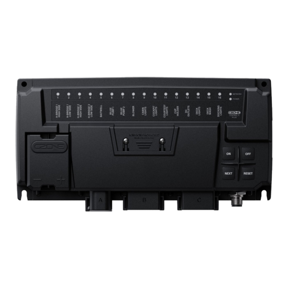
EN / CZone® Control X User & Installation Manual CONTROL X OVERVIEW Figure 1. Product Overview Component Circuit Status Indication (Will vary between Control X and Control X PLUS specs) Circuit Label Main Supply Terminal Panel Dipswitch Cover Connector A - DTP06-4S... -
Page 9: Led Indicators
EN / CZone® Control X User & Installation Manual LED INDICATORS A Connector B Connector Control X Plus B Connector Control X Figure 2. LED Indicators 1. Circuit Status LED’s Colour Description Channel Off Green Solid On Channel On 1 Red Flash... -
Page 10: Capacitive Touch Panel
NOTE - A long (200ms) press is required for operation of the touch pad buttons. NOTE - A Control X with any circuit forced ON via manual override will not be able to be put to sleep until the circuit has been reset. This is designed as a failsafe / get home state in case something on the network is forcing the system to sleep. -
Page 11: System Example
EN / CZone® Control X User & Installation Manual SYSTEM EXAMPLE Figure 4. CZone Control X PLUS System Example... -
Page 12: Installation
• Ensure circuit labels are fitted and all channels labelled correctly The Control X must be mounted at least 50mm away from high current carrying conductors such as anchor • winches, bow thruster cables, speakers, transformers and other high inductive loads. -
Page 13: Mounting
PLANNING Make a list of all inputs and outputs to be wired to the Control X and take note of the output channel ratings and functions as shown in Figure 7 and Figure 8. Assign each input and output to a channel on the Control X ensuring loads are wired to the appropriate channel for the functionality required. -
Page 14: Figure 7. Control X Plus Channel Specifications
EN / CZone® Control X User & Installation Manual Control X Plus Channel Notes 4x 15A High Side Outputs or 2x H-Bridge – 50A Connector Max H-Bridge channels ... -
Page 15: Figure 8. Control X Channel Speifications
EN / CZone® Control X User & Installation Manual Control X Channel Notes 12x 10A High Side Outputs or 12x Full SI Inputs – 80A Connector Max ... -
Page 16: Connections
5. Insert the connector into the Control X PLUS until it clicks into place. 6. Secure and neaten up the cables against the bulkhead to reduce the strain on the connectors. NOTE – Connector A on the Control X will be sealed from the factory. No blanking plug will be required. - Page 17 4. Connect NMEA2000 network 1. Connect a NMEA2000 drop cable from the Control X to a NMEA2000 backbone. 2. Ensure the NMEA2000 network is properly terminated and connected to a 12V power source (Do not power up network yet).
-
Page 18: Figure 10. Control X Main Supply Wiring
2. The positive cable must be of sufficient size to carry the maximum current of all loads connected to the Control X and have a fuse/circuit breaker rated to protect the cable, volt drop should be kept to a minimum. -
Page 19: Set Dipswitch
8. Check the software version of all modules on the network, including the Control X, with the CZone Configuration Tool and update if necessary. 9. Write configuration file to the Control X and the rest of the CZone modules on the system (Refer to the CZone Configuration Tool Instructions for details on how to configure the Control X). -
Page 20: Circuit Labeling
5 H-Bridge Motor Control 2 x 15A H-Bridge channels are included on the Control X PLUS allowing reversing motors to be connected directly to the module. The channels are available on Plug A. A combination of 1x H-Bridge output and 2x single channel outputs, or 2x H-Bridge outputs can be configured. -
Page 21: Bilge Pump Monitoring
EN / CZone® Control X User & Installation Manual 6 Bilge Pump Monitoring The Control X has advanced bilge pump functionality on all high side output channels, (Connector A and configured Connector B circuits). This allows pump control and external (automatic) voltage detection from a single wire. CZone... -
Page 22: Czone Switch Input Resistor Module (Czone Mux)
Mating Connector Part Numbers Available In Section 9, Ordering Information Notes: GND for the CZone MUX must return to the same module the Resistor Module is connected to. • The total wire resistance (signal wire and the GND wire) must be kept under ~10 ohms. -
Page 23: Control X Advanced Features
WIPER SYNCHRONISATION The Control X has an internal wiper motor controller for single and dual speed wiper motors. Up to 8 motors can be synchronized on the same module. The wiper motor control has fast and slow speed options as well as 3 configurable intermittent timer settings. -
Page 24: Rgbw Led Lighting Control
The Control X introduces an RGBW light controller built into the module for simplified installation and seamless lighting control as part of the CZone system. The Control X has a single RGBW lighting zone, and the Control X PLUS has two independent RGBW lighting zones. -
Page 25: Ordering Information
EN / CZone® Control X User & Installation Manual 9 Ordering Information PARTS AND ACESSORIES Part Number Description 80-911-0230-00 CZONE CONTROL X PLUS C/W CONNECTORS 80-911-0230-01 CZONE CONTROL X PLUS INTERFACE ONLY 80-911-0231-00 CZONE CONTROL X C/W CONNECTORS 80-911-0231-01 CZONE CONTROL X INTERFACE ONLY... -
Page 26: Technical Specifications
EN / CZone® Control X User & Installation Manual 10 Technical Specifications Specifications Circuit protection Software Fusing (Configurable using CZone Configuration Tool) NMEA2000 connectivity 1 x CAN Micro-C port, 1 LEN Output wire range 0.5 - 6mm (24AWG – 8AWG) -
Page 27: Dimensions
EN / CZone® Control X User & Installation Manual DIMENSIONS Figure 17. CZone Control X Dimensions... -
Page 28: Compliance
EN / CZone® Control X User & Installation Manual 11 COMPLIANCE... - Page 29 EN / CZone® Control X User & Installation Manual...
Need help?
Do you have a question about the Control X and is the answer not in the manual?
Questions and answers