Table of Contents
Advertisement
Quick Links
Advertisement
Table of Contents

Related Manuals for CZone RV1

Summary of Contents for CZone RV1
- Page 1 User & Installation Manual V1.0...
- Page 2 EN / CZone® RV1 Copyright This document is copyright 2018 under the Creative Commons agreement. Rights are granted to research and reproduce elements of this document for non-commercial purposes on the condition that BEP is credited as the source. Electronic re-distribution of the document in any format is restricted, to maintain quality and version control.
-
Page 3: Table Of Contents
GENERAL INFORMATION Use of this manual Guarantee Specifications Quality Validity Of This Manual Liability Changes To The RV1 MODULE SAFETY AND INSTALLATION PRECAUTIONS Warnings And Symbols Use For Intended Purpose Organizational Measures Maintenance And Repair General Safety and Installation Precautions... - Page 4 Table of Figures Figure 1. RV1 Overview ........................... 8 Figure 2. LED Indicators .......................... 9 Figure 3. CZone COI & Masterbus System Example ................11 Figure 4. TE Connectivity, Pro-Crimper lll ....................12 Figure 5. RV1 Mounting ......................... 13 Figure 6. RV1 Connections ........................18 Figure 7.
-
Page 5: General Information
RV1 MID SPEC 80-911-0221-00 It is obligatory that every person who works on or with the RV1 is completely familiar with the contents of this manual, and that he/she carefully follows the instructions contained herein. Installation of, and work on the RV1, may be carried out only by qualified, authorized and trained personnel, consistent with the locally applicable standards and taking into consideration the safety guidelines and measures (chapter 2 of this manual). -
Page 6: Safety And Installation Precautions
• Connection and protection must be done in accordance with local standards Do not work on the RV1 or system if it is still connected to a power source. Only allow changes in your • electrical system to be carried out by qualified electricians ... -
Page 7: Overview
By consolidating the functionality of multiple CZone modules into one compact unit, RV1 reduces system cost, complexity and installation time. RV1 enables RV builders to meet customer expectations for smart, automated and connected systems at an affordable price point. FEATURES 76 channels in a robust, compact enclosure ensures a single module digital switching solution across a wide •... -
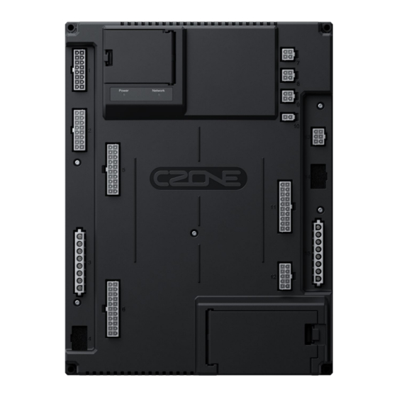
Page 8: Rv1 Overview
EN / CZone® RV1 RV1 OVERVIEW Figure 1. RV1 Overview Component Component Real Time Clock Battery Holder Connector 7, CZone NMEA2000 USB Interface Connector 8, RV-C Dipswitch Connector 9, Slave CAN BUS USB Function Button Connector 10, LIN BUS Power Indicator LED... -
Page 9: Led Indicators
Red Flash Network traffic USB PORT The USB port on the RV1 allows system software updates and configuration files to be loaded from a USB Memory Stick. The Power LED is used on the RV1 as the USB status indicator. 3.6.1 General Requirements &... -
Page 10: Reading Configuration From Network
To read the existing configuration from the network to the USB drive you must: 1. Insert a USB drive into the RV1 with NO existing (*.zcf or *.czfwp) files in the root folder. 2. Press the USB button for 5sec or until the Power LED flashes RED. -
Page 11: System Example
Inputs Slide Outs - High Awnings - Current Level Jacks - H-Bridge - Generator - HVAC Current - 3rd Party Controllers Outputs Lights - Refrigeration - Current Stereo - Outputs FUSE FUSE Figure 3. CZone COI & Masterbus System Example... -
Page 12: Installation
Obey the following stipulations during installation: • Ensure the RV1 is located in a cool, dry location. Ensure the RV1 is located in an easily accessible location for firmware and configuration updates. • Ensure indicator LED’s are visible for troubleshooting. -
Page 13: Mounting
EN / CZone® RV1 MOUNTING When mounting the RV1, a few guidelines must be kept in mind. A feature of the RV1 is a built-in accelerometer for future level monitoring capabilities, so mounting location must be thoroughly thought out. The RV1 can be mounted on any solid surface within the RV. -
Page 14: Planning
EN / CZone® RV1 PLANNING Make a list of all inputs and outputs to be wired to the RV1 and take note of the channel ratings and functions • as shown in the tables below. • When planning DC battery cabling, be sure to follow specifications for correct wiring of battery, 24hr loads, and charging systems. - Page 15 Switch to Pos or Neg • Battery Neg (Optional) Switch Input 1 can also be • Switch Input 5 used to wake RV1 from sleep Switch Input 6 mode Switch Input 7 Switch Input 8 Battery Neg (Optional) Signal Input 1...
- Page 16 EN / CZone® RV1 Connector 6 – 20x DC Outputs 5A Function Notes DC Output 5A 1 DC Output 5A 2 Channel Features DC Output 5A 3 Current monitoring, software • DC Output 5A 4 fusing and PWM all channels...
- Page 17 EN / CZone® RV1 Connector 13 6x DC Outputs 10A Function Notes Channel Features DC Output 10A 1 Current monitoring software DC Output 10A 2 • fusing and PWM all channels DC Output 10A 3 • Parallel up to 6 outputs...
-
Page 18: Connections
Figure 6. RV1 Connections 1. Connect NMEA2000 network 1. The RV1 Module uses automotive network connectors for the NMEA2000 network. BEP’s RV-C network component range part numbers are available in (6.2 Ordering Information). 2. Connect NMEA2000 drop cable from the RV1 to NMEA2000 backbone. -
Page 19: Figure 7. Rv1 Dc Supply Wiring
7. Connect 24hr Loads (Optional) 1. If built-in State of Charge monitoring is to be used, then connect 24hr loads to the RV1’s ‘Load’ Stud. Take extra care when wiring the 24hr loads to ensure that no 24hr load is connected directly to the battery. -
Page 20: Set Dipswitch
6. Check the software version on the RV1 with the CZone Configuration Tool and update if necessary. 7. Write configuration file to the RV1 and the rest of the CZone modules on the system (Refer to the CZone Configuration Tool Instructions for details on how to configure the RV1). -
Page 21: Specifications
Dimensions (W x H x D) 233 x 307 x 58mm (9.17 x 12.09 x 2.28”) Weight 1.4kg (3lb) Compliance CE, RCM, UK-CA NMEA 2000 PGN’S NMEA 2000 PGN’s sent from the RV1 PGN Number Description Fields 127508 Battery Status Battery Voltage, Battery Current... -
Page 22: Dimensions
EN / CZone® RV1 DIMENSIONS 233mm [9 3/16"] 222mm [8 3/4"] 233mm [9 3/16"] Figure 9. Dimensions... -
Page 23: Ordering Information
EN / CZone® RV1 6 ORDERING INFORMATION RV1 PART NUMBERS AND ACCESSORIES Part Number Description 80-911-0221-00 RV1 MID SPEC KIT 80-911-0225-00 RV1 MID SPEC CONNECTOR KIT MSC-RV-KIT RV1 FASTENER KIT SPARE RV-C CABLING PART NUMBERS Part Number Description 80-911-0206-00 RV-C 4WAY TEE... -
Page 24: Figure 11. Connector Kit Parts List
EN / CZone® RV1 CONNECTOR KIT PARTS LIST Description & TE Plug Connector Quantity Image Wire Gauge Part Number H-Bridge 5A 1-1969597-6 26-16AWG (0.15-1.5mm²) Analogue Input 5,11 2-1969597-0 26-16AWG (0.15-1.5mm²) DC Output 5A 2-1969597-2 26-16AWG (0.15-1.5mm²) DC Output 0.5A 1-1969597-0 26-16AWG (0.15-1.5mm²) - Page 25 EN / CZone® RV1 7 COMPLIANCE...
- Page 26 EN / CZone® RV1...
Need help?
Do you have a question about the RV1 and is the answer not in the manual?
Questions and answers